PLC Ladder Logic
The easiest visual programming language for controls is a called ladder logic or ladder diagram when it comes to a PLC programming language which is one of the best ones to learn because of the impact and the ability to have one of the best jobs or careers.
YOU DO NOT WANT TO MISS THIS ONE!
Ladder diagram systems are the best programming language to learn and the smart thing that the designers did was make it very similar to standard electrical circuits that used relays and act just like a single line diagram in some instances.
If you happen to be in the electrical field already then you probably have experience with wiring relays or even reading prints for relay controls then learning logic will be extremely easy and make the process much faster.
Are you interested in a ladder logic tutorial?
I was, here are just a few highlights of my career so far after 18 years in automation:
- Made over 120K a year for the past 14 years
- Better Self-confidence
- Better career
- Better benefits
- Better opportunities
- Easier problem-solving in life
- Being able to take care of my family without worries
- Learned that with effort, all things can be accomplished
- Easier to develop plans
I have put together a great reference to break down the process and prove this is your place to turn to learn everything you need to know about ladder diagram plc programming.
After this tutorial, you will be able to start a plc program and understand what it takes to be successful so I highly recommend that you take a few online plc programming courses to better your growth leave you without a question, an expert in the industry.
Are you ready to get started? Let’s get to it!
I want to share with you the knowledge I have learned in PLC controls & automation so that you can be a better version of yourself tomorrow than you are today, after all, that is what I strive to do myself. To be a better version of myself tomorrow than I am today, in doing so we continuously improve our lives & those around us.
With that said, there are several videos on this page & over 40 on this website that can help you learn.
PLC Programming for Beginners
This programming language is the simplest of the programming schemes but has also been known as a ladder diagram or LD for short, it has been come to be known as a primary name of ladder diagram logic instead of these multiple names. That is also what I will call it in this tutorial.
The main reason for the common name and everyone agreeing on this is basically because ladder by ladder the program is scanned and executed and the scheme of programming is to make the logic work. Meaning, if you can think it then you can logically make it happen if the thought aligns with real-world logic.
Basically just a bunch on 1s and 0s or better known to be referenced as the binary decimal code.
Of course with RSLogix 5000 and Studio 5000, there is an understanding of how that binary code works which leads to setting up I/O cards no matter what plc brand you are using but in my examples.
I show RSLogix 5000 or Studio 5000 so here is a quick reference to set up and scale a PLC analog input card, with this said, the ladder is made up of other I/O cards for inputs and Outputs which can be referenced in my Adding I/O in Studio 5000 program video but ladder diagram logic is mainly a to set for bits logic operations.
There is an organization that sets the standards for PLC ladder logic which is called PLCOpen, They have named a standard is called IEC 61131-3.
Well, even though we are talking about ladder examples, it would not be fair to act like this is the only plc programming language.
Here is a quick list of all the plc programming languages:
- Ladder Logic
- Function Block Diagram
- Structured Text
- Sequential Function Chart
Introduction PLC ladder logic
First, learning how to read the logic and is easy as I said if you know how to read an electrical schematic then rung by rung and ladder by ladder, it flows the same way. A logic diagram is laid out from left to right and the operands are located on the right side of the screen just like an electrical schematic.
We will be talking about the operands like OTE, OTL, OTU, XIC, and XIO a little later in this ladder logic tutorial and with that being said, reading the plc code is first to know about.
Is it easy to read? Yes….
In Rockwell software such as RSLogix 5000 or Studio 5000, they make reading the logic very easy by making it a bit colored if active and not if not active. Generally, when the software is installed the default colors are green if active and not if not active. Note that some bits are used in the inverse function like the difference in an XIC or XIO instruction set.
You can draw it on paper first for ideas….
What has helped me in the past is to draw out the start of the logic on a plain sheet of paper to use as a scratch pad as in the examples I talked about.
18 years ago, I started learning PLC logic and when I did, I often compared it to standard relay logic so drawing it out helped me make sense of it and then it was just learning the software and the future belongs to Rockwell so, in my opinion, it is best to learn RSlogix 500, RSlogix 5000, and Studio 5000 but no worries.
We can help!
To start off, we have training modules designed for beginners and advanced users as well but just to take some of that weight off your shoulders, RSlogix 5000 and Studio 5000 are the same with minor differences so you really just need to learn RSLogix 500 and Studio 5000.
Check out what we offer —-> Training Center Overview
There is an executive order of operation…
The last reason for drawing ladder diagrams horizontal is to set the order of execution. Order of execution is how the PLC will run your control logic. To be more precise in what order your logic instructions will be executed by the PLC. A PLC will always start at the top of your ladder diagram logic and then execute its way down
Ladder logic symbols
An XIC instruction
The first instruction for plc ladder logic that we are going to talk about is the examine if closed or better known as XIC which is an instruction that is active or true when the bit status is in a 1 state and not in a 1 state of the binary condition.
Meaning, as we talked about earlier in this article a bit is binary and computer programming is binary so 1s and 0s, and with that being said then when the bit transitions from a 0 to a 1. In the words of Rockwell, the XIC instruction examines the data bit to see if it is true.
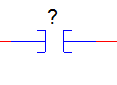
- If the binary bit is true, the rung condition out is set to true.
- If the binary bit is false, the rung condition out is cleared to false.
An XIO instruction
Next, we talk about the counterpart to the XIC, and this instruction is examined if open or better known as the XIO which is an instruction that is active when the bit status is in a 0 state instead of a 1 state of the binary condition.
This instruction acts slightly differently, in fact, acts in the opposite of the first instruction, in the software it is active when the binary status a 0. In the words of Rockwell, the XIO instruction examines the data bit to see if it is false.
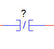
- If the binary bit is true, the rung-condition-out is cleared to false.
- If the binary Bit is false, the rung-condition-out is set to true.
An OTE instruction
When it comes to watching bit states and their states, XIC and XIO are used in many different ways but as far as controlling bits and making them change states then you need to use an OTE instruction which is an output control.
The OTE instruction sets a binary bit either on or off meaning, either a 1 or a 0, and is done when a rung is true or false. If the rung is true then the OTE is high or in other words, set to a 1, and when the rung is not true or all elements are not made then the OTE is set to a 0.
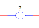
- When the OTE instruction is true, the controller sets the data bit.
- When the OTE instruction is false, the controller clears the data bit.
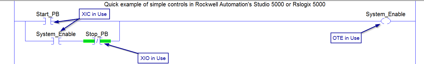
Using XIC, XIO, and OTE instructions
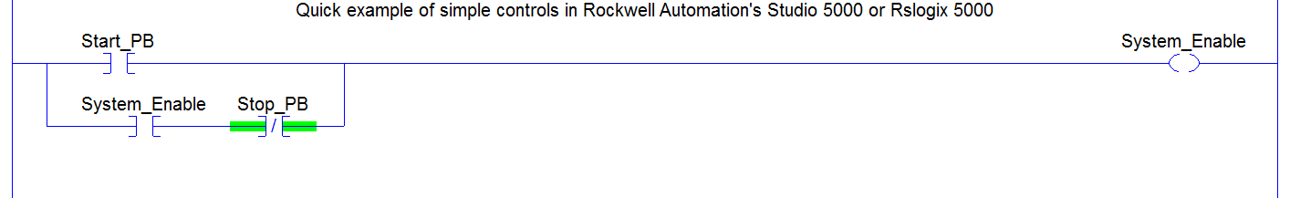
In the example I have below, the Start_PB bit is an XIC instruction so in this rung if the Start_PB is in a 1 state or high then the OTE instruction will be on or set to a 1 state so in other words, if the Start_PB is pressed then the System_Enable will be on and stay on until the Stop_PB is pressed because the Stop_PB is an XIO so if pressed then it is not active.
Keep in mind that this example shows these bits in momentary pushbuttons and are not an example of a maintained pushbutton situation. The rung would have to be slightly modified if the pushbuttons were a maintained switch.
So now let’s look at the same exact rung after the Start_PB (XIC) has been pressed which cause the System_Enable (OTE) to trigger on then the System_Enable (XIC) and the Stop_PB (XIO) hold the plc ladder logic true and the System_Enable bit remains on until the Stop_PB would be pressed.
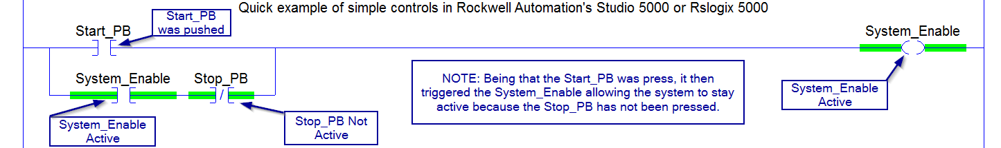
Studio 5000 simple active rung
Here is what that would look like if the Start_PB were pressed the System_Enable is triggered then the Stop_PB was pressed and the rung unlatches.
Ladder Logic Examples with Timers
Studio 5000 Timer On instruction
To start off the timer section, the very first timer we need to discuss is the TON instruction which is a timer on delay, and to talk about how it works, there are three elements that you need to be aware of.
The first is the timer name which is just a tag name that you give it, next there is a preset which is the amount of the time that you want to delay the timer to become done, and then there is an Accum which is the current accumulated time of the timer.
The TON instruction is a non-retentive timer that accumulates time when the instruction is enabled.
How a Timer On Runs
A timer runs by subtracting the time of its last scan from the current time:
ACC = ACC + (current_time – last_time_scanned)
After it updates the ACC, the timer sets last_time_scanned = current_time. This gets the timer ready for the next scan.

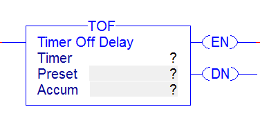
Studio 5000 Timer Off instruction
The next timer is the TOF instruction which is a timer off which is holds an active done bit as long as the rung is true and remains to hold the done bit of the timer after the rung is not true until the time limit has run out.
This timer acts opposite of the TON timer which is very helpful if you are trying to have a rung or system stay working without and ignore a blip in a system or in other words can be used as a debounce if implemented correctly. The TOF instruction is a non-retentive timer that accumulates time when the instruction is enabled.
How a Timer Off Runs
A timer runs by subtracting the time of its last scan from the current time:
ACC = ACC + (current_time – last_time_scanned)
After it updates the ACC, the timer sets last_time_scanned = current_time. This gets the timer ready for the next scan.
Studio 5000 Retentive Timer instruction
The last timer is the RTO which is a retentive timer meaning, if the timer is active then it retains the amount of time it was active until a reset command is triggered. If the rung is true and the timer starts then it starts timing then the done bit reacts based upon the preset of the RTO timer.
If the preset to the timer is 5000ms then as soon as the timer reaches or exceeds 5000ms then the done bit is true however if the time does not exceed the preset value then the done bit is not true. The RTO instruction is a retentive timer that accumulates time when the instruction is enabled.
How an RTO Timer Runs
A timer runs by subtracting the time of its last scan from the current time:
ACC = ACC + (current_time – last_time_scanned)
After it updates the ACC, the timer sets last_time_scanned = current_time. This gets the timer ready for the next scan.

Ladder logic Tutorial – Alias I/O
Since we started this plc tutorial with how a plc works and what it is then continued to what ladder logic symbols are then talked about timers and showed how they work then it is only fair to continue the programming education and learn how to link inputs and outputs to tags or alias tag.
The best way to learn is to keep the train rolling and keep teaching.
The very best way, in my opinion, is to watch videos and have video training because you can watch it as many times as needed.
I know for me, it is like watching a movie, we often miss the details the first time so I watch things twice but how can I really say that for training being that there were no training videos for plc ladder logic when I first learned over 18 years ago.
I wish there was so without saying much more here is the last video for this article.
Ladder Logic
The easiest visual programming language for controls is a called ladder logic or ladder diagram when it comes to a PLC programming language which is one of the best ones to learn because of the impact and the ability to have one of the best jobs or careers.
YOU DO NOT WANT TO MISS THIS ONE!
Ladder diagram systems are the best programming language to learn and the smart thing that the designers did was make it very similar to standard electrical circuits that used relays and act just like a single line diagram in some instances.
If you happen to be in the electrical field already then you probably have experience with wiring relays or even reading prints for relay controls then learning logic will be extremely easy and make the process much faster.
Are you interested in a ladder logic tutorial?
was, here are just a few highlights of my career so far after 18 years in automation:
- Made over 120K a year for the past 14 years
- Better Self-confidence
- Better career
- Better benefits
- Better opportunities
- Easier problem-solving in life
- Being able to take care of my family without worries
- Learned that with effort, all things can be accomplished
- Easier to develop plans
I have put together a great reference to break down the process and prove this is your place to turn to learn everything you need to know about ladder diagram plc programming.
After this tutorial, you will be able to start a plc program and understand what it takes to be successful so I highly recommend that you take a few online plc programming courses to better your growth leave you without a question, an expert in the industry.
Are you ready to get started? Let’s get to it!
I want to share with you the knowledge I have learned in PLC controls & automation so that you can be a better version of yourself tomorrow than you are today, after all, that is what I strive to do myself. To be a better version of myself tomorrow than I am today, in doing so we continuously improve our lives & those around us.
With that said, there are several videos on this page & over 40 on this website that can help you learn.
PLC Programming for Beginners
This programming language is the simplest of the programming schemes but has also been known as a ladder diagram or LD for short, it has been come to be known as a primary name of ladder diagram logic instead of these multiple names. That is also what I will call it in this tutorial.
The main reason for the common name and everyone agreeing on this is basically because ladder by ladder the program is scanned and executed and the scheme of programming is to make the logic work.
Meaning, if you can think it then you can logically make it happen if the thought aligns with real-world logic. Basically just a bunch on 1s and 0s or better known to be referenced as the binary decimal code.
Of course with RSLogix 5000 and Studio 5000 there is an understanding of how that binary code works which leads into setting up I/O cards no matter what plc brand you are using but in my examples.
I show RSlogix 5000 or Studio 5000 so here is a quick reference to set up and scale a PLC analog input card, with this said, the ladder is made up of other I/O cards for inputs and Outputs which can be referenced in my Adding I/O in Studio 5000 program video but ladder diagram logic is mainly a to set for bits logic operations.
There is an organization that sets the standards for PLC ladder logic which is called PLCOpen, They have named a standard is called IEC 61131-3.
Well, even though we are talking about the ladder, it would not be fair to act like this is the only plc programming language.
Here is a quick list of all the plc programming languages:
- Ladder Logic
- Function Block Diagram
- Structured Text
- Sequential Function Chart
Introduction PLC ladder logic
First, learning how to read the logic and that is easy as I said if you know how to read an electrical schematic then rung by rung and ladder by ladder, it flows the same way. A logic diagram is laid out from left to right and the operands are located on the right side of the screen just like an electrical schematic.
We will be talking about the operands like OTE, OTL, OTU, XIC, and XIO a little later in this ladder logic tutorial and with that being said, reading the plc code is first to know about.
Is it easy to read? Yes….
In Rockwell software such as RSLogix 5000 or Studio 5000, they make reading the logic very easy by making a bit colored if active and not if not active.
Generally, when the software is installed the default colors are green if active and not if not active. Note that some bits are used in the inverse function like the difference in an XIC or XIO instruction set.
You can draw it on paper first for ideas….
What has helped me in the past is to draw out the start off the logic on a plain sheet of paper to using as a scratch pad as in the examples I talked about, 18 years ago, I started learning PLC logic.
And when I did, I often compared it to standard relay logic so drawing it out helped me make sense of it, and then it was just learning the software and the future belongs to Rockwell so, in my opinion, it is best to learn RSlogix 500, RSlogix 5000, and Studio 5000 but no worries.
We can help!
To start off, we have training modules designed for beginners and advanced users as well but just to take some of that weight off your shoulders, RSlogix 5000 and Studio 5000 are the same with minor differences so you really just need to learn RSLogix 500 and Studio 5000. Check out what we offer —-> Training Center Overview
There is an executive order of operation…
The last reason for drawing ladder diagrams horizontal is to set the order of execution. Order of execution is how the PLC will run your control logic. To be more precise in what order your logic instructions will be executed by the PLC. A PLC will always start at the top of your ladder diagram logic and then execute its way down
Ladder logic symbols
An XIC instruction
The first instruction for plc ladder logic that we are going to talk about is the examine if closed or better known as XIC which is an instruction that is active or true when the bit status is in a 1 state and not in a 1 state of the binary condition.
Meaning, as we talked about earlier in this article a bit is binary and computer programming is binary so 1s and 0s, and with that being said then when the bit transitions from a 0 to a 1. In the words of Rockwell, the XIC instruction examines the data bit to see if it is true.
- If the binary bit is true, the rung condition out is set to true.
- If the binary bit is false, the rung condition out is cleared to false.
An XIO instruction
Next, we talk about the counterpart to the XIC, and this instruction is examined if open or better known as the XIO which is an instruction that is active when the bit status is in a 0 state instead of a 1 state of the binary condition.
This instruction acts slightly differently, in fact, acts in the opposite of the first instruction, in the software it is active when the binary status a 0. In the words of Rockwell, the XIO instruction examines the data bit to see if it is false.
- If the binary bit is true, the rung-condition-out is cleared to false.
- If the binary Bit is false, the rung-condition-out is set to true.
An OTE instruction
When it comes to watching bit states and their states, XIC and XIO are used in many different ways but as far as controlling bits and making them change states then you need to use an OTE instruction which is an output control.
The OTE instruction sets a binary bit either on or off meaning, either a 1 or a 0, and is done when a rung is true or false. If the rung is true then the OTE is high or in other words, set to a 1, and when the rung is not true or all elements are not made then the OTE is set to a 0.
- When the OTE instruction is true, the controller sets the data bit.
- When the OTE instruction is false, the controller clears the data bit.
Using XIC, XIO, and OTE instructions
In the example I have below, the Start_PB bit is an XIC instruction so in this rung, if the Start_PB is in a 1 state or high then the OTE instruction will be on or set to a 1 state so in other words if the Start_PB is pressed then the System_Enable will be on and stay on until the Stop_PB is pressed because the Stop_PB is an XIO so if pressed then it is not active.
Keep in mind that this example shows these bits in momentary pushbuttons and is not an example of a maintained pushbutton situation. The rung would have to be slightly modified if the pushbuttons were a maintained switch.
So now let’s look at the same exact rung after the Start_PB (XIC) has been pressed which cause the System_Enable (OTE) to trigger on then the System_Enable (XIC) and the Stop_PB (XIO) hold the plc ladder logic true and the System_Enable bit remains on until the Stop_PB would be pressed.
Studio 5000 simple active rung
Here is what that would look like if the Start_PB were pressed the System_Enable is triggered then the Stop_PB was pressed and the rung unlatches.
Ladder Logic Examples with Timers
Studio 5000 Timer On instruction
To start off the timer section, the very first timer we need to discuss is the TON instruction which is a timer on delay and to talk about how it works, there are three elements that you need to be aware of.
The first is the timer name which is just a tag name that you give it, next there is a preset which is the amount of the time that you want to delay the timer to become done, and then there is an Accum which is the current accumulated time of the timer.
The TON instruction is a non-retentive timer that accumulates time when the instruction is enabled.
How a Timer On Runs
A timer runs by subtracting the time of its last scan from the current time:
ACC = ACC + (current_time – last_time_scanned)
After it updates the ACC, the timer sets last_time_scanned = current_time. This gets the timer ready for the next scan.
Studio 5000 Timer Off instruction
The next timer is the TOF instruction which is a timer off which is holds an actively done bit as long as the rung is true and remains to hold the done bit of the timer after the rung is not true until the time limit has run out.
This timer acts opposite of the TON timer which is very helpful if you are trying to have a rung or system stay working without and ignore a blip in a system or in other words can be used as a debounce if implemented correctly.
The TOF instruction is a non-retentive timer that accumulates time when the instruction is enabled.
How a Timer Off Runs
A timer runs by subtracting the time of its last scan from the current time:
ACC = ACC + (current_time – last_time_scanned)
After it updates the ACC, the timer sets last_time_scanned = current_time. This gets the timer ready for the next scan.
Studio 5000 Retentive Timer instruction
The last timer is the RTO which is a retentive timer meaning, if the timer is active then it retains the amount of time it was active until a reset command is triggered. If the rung is true and the timer starts then it starts timing then the done bit reacts based upon the preset of the RTO timer.
If the preset to the timer is 5000ms then as soon as the timer reaches or exceeds 5000ms then the done bit is true however if the time does not exceed the preset value then the done bit is not true. The RTO instruction is a retentive timer that accumulates time when the instruction is enabled.
How an RTO Timer Runs
A timer runs by subtracting the time of its last scan from the current time:
ACC = ACC + (current_time – last_time_scanned)
After it updates the ACC, the timer sets last_time_scanned = current_time. This gets the timer ready for the next scan.
Ladder logic Tutorial – Alias I/O
Since we started this plc tutorial with how a plc works and what it is then continued to what ladder logic symbols are then talked about timers and showed how they work then it is only fair to continue the programming education and learn how to link inputs and outputs to tags or alias tag.
The best way to learn is to keep the train rolling and keep teaching.
The very best way, in my opinion, is to watch videos and have video training because you can watch it as many times as needed.
I know for me, it is like watching a movie, we often miss the details the first time so I watch things twice but how can I really say that for training being that there were no training videos for plc ladder logic when I first learned over 18 years ago.
I wish there was so without saying much more here is the last video for this article.
Our PLC Training Platform
This training platform that I made is like no other and the best quality on the internet so you get the very best and need to look no further. I have fully developed training that shows everything from free training to paid but most importantly, all areas of plc and HMI training.
I understand what it’s like trying to keep up with demanding workloads so I wanted to share one thing that helps me out.
The 1st phorm energy drink, 10x better than Monster or any other off-the-shelf drink.
Get a case and try it, you will thank me later.
Here is a picture of my personal favorite flavor.
