Need help with Motion Axis Position Cams?
Need help with
Motion Axis Position Cams
Keeping up with Technology
Motion Axis Position Cam (MAPC)
To start off with, thank you for visiting Online PLC Support and I very much appreciate your support. This site is designed to help anyone looking to further their knowledge on Rockwell Automation software and in this article, I will be going over the RSLogix 5000 motion axis position cam instruction in a simple programming example that I made on my YouTube channel.
How does a MAPC work?
For the motion axis position cam or better known as the PCAM instruction, you need to first look at the requirements of the instruction but before we get into that let’s quickly go over how the instruction works. There is a master axis and a slave axis in which are used in this instruction where the slave axis is tied to the master axis based on the position designated in the cam profile or cam array.
In other words, the slave axis will be commanded to move based on the position of the master axis and the setup of the instruction.
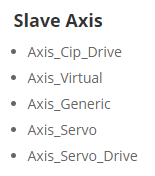
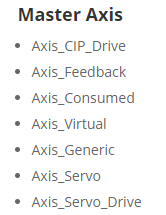
Now that we have briefly talked about the way the process works, let’s talk about the elements of the PCAM instruction. There is a slave axis and a master axis which are the first two input data points of the instruction and are mentioned above. Next is the motion control input which is the name of the instruction that you give it, this is done by right-clicking the tab and selecting create new if you are setting this up from scratch. It gives the logic the process structure it needs to be used.
Next is the direction input tab which is the direction the slave axis will be used in relation to the master axis and the camming. There are 4 options to select from which are Same, Opposite, Reverse, and Unchanged.
Types:
- Same – the slave axis position values are in the same sense as the master.
- Opposite – the slave axis position values are in the opposite sense of the master’s.
Or relative to the current or previous camming direction:
- Reverse – the current or previous direction of the position cam is reversed on execution. When executed for the first time with Reverse selected, the control defaults the direction to Opposite.
- Unchanged – this allows other cam parameters to be changed without altering the current or previous camming direction. When executed for the first time with.
Cam Profile
Now we come to the most important part of the instruction, in my opinion, the cam profile. First, you want to make sure that you make the tag for the cam profile an array having the proper number of data points that you want to use in your profile when you build it. This does not automatically size, you have to define data size when making the tag and select the Dim size. Meaning, if our tag was named Cam_Profile and we had a data size of 100 then when we make the tag, we would select the dim size to 100.
it would look like this:
Cam_Profile[100]
Which leaves you with 100 points of data that can be used to form the cam and are from 0 through 99. It is also important to note that when you select the tag to be used in this instruction that you use the very start of the array which would look like this in the example I just gave. Cam_Profile[0]
Please note: With larger type arrays such as the one shown, it is often easier to use an excel spreadsheet to build the cam then copy and paste it into the cam editor of the MAPC instruction.
Here is a helpful video showing this process and how to use Microsoft Excel to build a Servo Cam.
This video plainly shows to benefit of using such tools to make a cam or build a cam yourself, not to say that you can’t manually enter it or program a cam building instruction as well….all methods will work just fine.
Important note: Decreasing the master scaling value or increasing the slave axis of the cam increase the velocity and the accelerations of the motion required, in the troubleshooting, this can be a leading cause of a servo fault if the system exceeds the drives system capacities.
Next going down the list are Execution mode, Execution Schedule, Master Lock Position, Cam Lock Position, Master Reference, and Master Direction. Out of all of these, I will start with the Execution mode and schedule. The mode has three option to choose from which are Once, Continuous, and Persistent.
Execution Schedule
- Immediate – The slave axis is immediately locked to the master axis and the position camming process begins.
- Pending – lets you blend a new position cam execution after an in-process position cam is finished. When Pending is selected the following parameters are ignored: Master Axis, Master Lock Position, and Master Reference.
- Forward only – the cam profile starts when the master position crosses the Master Lock Position in the forward direction.
- Reverse only – the cam profile starts when the master position crosses the Master Lock Position in the reverse direction.
- Bi-directional – the cam profile starts when the master position crosses the Master Lock Position in either direction.
Execution Modes
If Once is selected by default in most cases, the cam motion of the slave axis starts only when the master axis moves into the range defined by the start and end points of the cam profile. When the master axis position is past the defined points then the slave axis stops and the process complete bit turns on.
When in Continuous is selected then once the instruction is started then it is executed indefinitely and when the master axis moves outside of the cam defined position then it will cause the cam to repeat itself and will run until stopped.
When the system is selected to Persistent the when the Master Axis moves beyond the defined range, cam motion on the Slave Axis stops and the PositionCamLockStatus bit is cleared. Slave motion resumes in the opposite direction when the Master Axis reverses and moves back into the cam profile range, at which time the PositionCamLockStatus bit is set.
Lock Position
The cam lock position parameter indicates when the starting point where the slave locks to the master based off of the cam profile points. Typical set up is starting at 0 but can be set to whatever your design requires, in some instances an offset is needed and this is where you can enter it so the cam has an offset. So if you choose to use an offset then keep in mind that the cam starting points of the slave axis is affected and will be shifted in the direction of the offset.
RSLogix 5000 Servo Motion Position Cam Profile Example – 15 minutes
Here is a simple set up that has been created to give you a visual representation of a MAPC instruction. I have much more detailed videos in my servo course that is called Advanced Servo Motion Mastery and has full modules that will leave no question to how a MAPC works and how to program but this video is just a simple set up to save you time and also give a quick example.
So to describe the video above, it lays out a very simple motion control set up with several motion axis position cam instructions. Also does not use any hardware as everything is emulated and is using virtual axis instead of a real-world axis or motors.
This is to show that you do not need the hardware if you wanted to practice this type of programming wherever you are and at low cost.
Allen Bradley RSLogix 5000 MAPC instruction with servo cam profile scaling
In the video, I talk about using scaling between the slave servo and the master servo in a cam profile that is being run in a MAPC instruction with RSlogix 5000 but is the same for Studio 5000.
Part of the video, I break down the scaling of the slave servo in relation to the master servo then show the effects based on a trend which shows a great example for understanding.
In the next part, I show the scaling of the master servo in relation to the slave servo then show the reaction of that setup. Finally, I show the reaction of both together then talk about scaling in general from a 3 to 1 or 9 to 3 being the same but still causes a stretched servo cam profile.
When it comes to making videos or producing this articles and such, I do this to add value to help people learn and to be honest, the better we all get then the better the training gets. In other words, we all grow so why not share?
What are your thoughts?
Did you learn something from the video or the article?
I would love to hear your feedback and am very interested in getting other viewpoints or topics that you would like to see.
Please visit my Patreon site to provide me with feedback and be able to submit a special request for this you would like to see.
Become a Member of this SPECIAL group today!
Thanks,
Shane
Motion Axis Position Cam (MAPC)
To start off with, thank you for visiting Online PLC Support and I very much appreciate your support. This site is designed to help anyone looking to further their knowledge on Rockwell Automation software and in this article, I will be going over the RSLogix 5000 motion axis position cam instruction in a simple programming example that I made on my YouTube channel.
How does a MAPC work?
For the motion axis position cam or better known as the PCAM instruction, you need to first look at the requirements of the instruction but before we get into that let’s quickly go over how the instruction works. There is a master axis and a slave axis in which are used in this instruction where the slave axis is tied to the master axis based on the position designated in the cam profile or cam array.
In other words, the slave axis will be commanded to move based on the position of the master axis and the setup of the instruction.
Now that we have briefly talked about the way the process works, let’s talk about the elements of the PCAM instruction. There is a slave axis and a master axis which are the first two input data points of the instruction and are mentioned above. Next is the motion control input which is the name of the instruction that you give it, this is done by right-clicking the tab and selecting create new if you are setting this up from scratch. It gives the logic the process structure it needs to be used.
Next is the direction input tab which is the direction the slave axis will be used in relation to the master axis and the camming. There are 4 options to select from which are Same, Opposite, Reverse, and Unchanged.
Types:
- Same – the slave axis position values are in the same sense as the master.
- Opposite – the slave axis position values are in the opposite sense of the master’s.
Or relative to the current or previous camming direction:
- Reverse – the current or previous direction of the position cam is reversed on execution. When executed for the first time with Reverse selected, the control defaults the direction to Opposite.
- Unchanged – this allows other cam parameters to be changed without altering the current or previous camming direction. When executed for the first time with.
Cam Profile
Now we come to the most important part of the instruction, in my opinion, the cam profile. First, you want to make sure that you make the tag for the cam profile an array having the proper number of data points that you want to use in your profile when you build it. This does not automatically size, you have to define data size when making the tag and select the Dim size. Meaning, if our tag was named Cam_Profile and we had a data size of 100 then when we make the tag, we would select the dim size to 100.
it would look like this:
Cam_Profile[100]
Which leaves you with 100 points of data that can be used to form the cam and are from 0 through 99. It is also important to note that when you select the tag to be used in this instruction that you use the very start of the array which would look like this in the example I just gave. Cam_Profile[0]
Please note: With larger type arrays such as the one shown, it is often easier to use an excel spreadsheet to build the cam then copy and paste it into the cam editor of the MAPC instruction.
Here is a helpful video showing this process and how to use Microsoft Excel to build a Servo Cam.
This video plainly shows to benefit of using such tools to make a cam or build a cam yourself, not to say that you can’t manually enter it or program a cam building instruction as well….all methods will work just fine.
Important note: Decreasing the master scaling value or increasing the slave axis of the cam increase the velocity and the accelerations of the motion required, in the troubleshooting, this can be a leading cause of a servo fault if the system exceeds the drives system capacities.
Next going down the list are Execution mode, Execution Schedule, Master Lock Position, Cam Lock Position, Master Reference, and Master Direction. Out of all of these, I will start with the Execution mode and schedule. The mode has three option to choose from which are Once, Continuous, and Persistent.
Execution Schedule
- Immediate – The slave axis is immediately locked to the master axis and the position camming process begins.
- Pending – lets you blend a new position cam execution after an in-process position cam is finished. When Pending is selected the following parameters are ignored: Master Axis, Master Lock Position, and Master Reference.
- Forward only – the cam profile starts when the master position crosses the Master Lock Position in the forward direction.
- Reverse only – the cam profile starts when the master position crosses the Master Lock Position in the reverse direction.
- Bi-directional – the cam profile starts when the master position crosses the Master Lock Position in either direction.
Execution Modes
If Once is selected by default in most cases, the cam motion of the slave axis starts only when the master axis moves into the range defined by the start and end points of the cam profile. When the master axis position is past the defined points then the slave axis stops and the process complete bit turns on.
When in Continuous is selected then once the instruction is started then it is executed indefinitely and when the master axis moves outside of the cam defined position then it will cause the cam to repeat itself and will run until stopped.
When the system is selected to Persistent the when the Master Axis moves beyond the defined range, cam motion on the Slave Axis stops and the PositionCamLockStatus bit is cleared. Slave motion resumes in the opposite direction when the Master Axis reverses and moves back into the cam profile range, at which time the PositionCamLockStatus bit is set.
Lock Position
The cam lock position parameter indicates when the starting point where the slave locks to the master based off of the cam profile points. Typical set up is starting at 0 but can be set to whatever your design requires, in some instances an offset is needed and this is where you can enter it so the cam has an offset. So if you choose to use an offset then keep in mind that the cam starting points of the slave axis is affected and will be shifted in the direction of the offset.
RSLogix 5000 Servo Motion Position Cam Profile Example – 15 minutes
Here is a simple set up that has been created to give you a visual representation of a MAPC instruction. I have much more detailed videos in my servo course that is called Advanced Servo Motion Mastery and has full modules that will leave no question to how a MAPC works and how to program but this video is just a simple set up to save you time and also give a quick example.
So to describe the video above, it lays out a very simple motion control set up with several motion axis position cam instructions. Also does not use any hardware as everything is emulated and is using virtual axis instead of a real-world axis or motors.
This is to show that you do not need the hardware if you wanted to practice this type of programming wherever you are and at low cost.
Allen Bradley RSLogix 5000 MAPC instruction with servo cam profile scaling
In the video, I talk about using scaling between the slave servo and the master servo in a cam profile that is being run in a MAPC instruction with RSlogix 5000 but is the same for Studio 5000.
Part of the video, I break down the scaling of the slave servo in relation to the master servo then show the effects based on a trend which shows a great example for understanding.
In the next part, I show the scaling of the master servo in relation to the slave servo then show the reaction of that setup. Finally, I show the reaction of both together then talk about scaling in general from a 3 to 1 or 9 to 3 being the same but still causes a stretched servo cam profile.
When it comes to making videos or producing this articles and such, I do this to add value to help people learn and to be honest, the better we all get then the better the training gets. In other words, we all grow so why not share?
What are your thoughts?
Did you learn something from the video or the article?
I would love to hear your feedback and am very interested in getting other viewpoints or topics that you would like to see.
Please visit my Patreon site to provide me with feedback and be able to submit a special request for this you would like to see.
Become a Member of this SPECIAL group today!
Thanks,
Shane