Studio 5000 – Using The Firmware Add-On Instruction
The intent of this post is to provide the AOI for you to download yourself then to teach how to use this Add-On instruction that detects the firmware of any device in your program’s I/O tree. This is designed to give a clear way to install this AOI in Studio 5000 then be able to program the logic required to get up & running by the time you finish it.
Here is a quick view of what it looks like after completely installed.

Table Of Contents
Importing the Add-On Instruction
Programming In Studio 5000 Using The Add-On Instruction
Adding The Data Collection Bit
Importing the Add-On Instruction
Open the PLC program that you would like to use the I/O module Add-On instruction in then highlight the Add-On Instruction folder in the controller organizer tab on the left hand side of the screen.
Importing an Add-On Instruction can be done while online with the PLC processor in RSLogix 5000 & Studio 5000, however, it is in the best practice that you do this while offline then download after the edits have been made.
In this example, we will be doing the work offline then downloading after for testing.
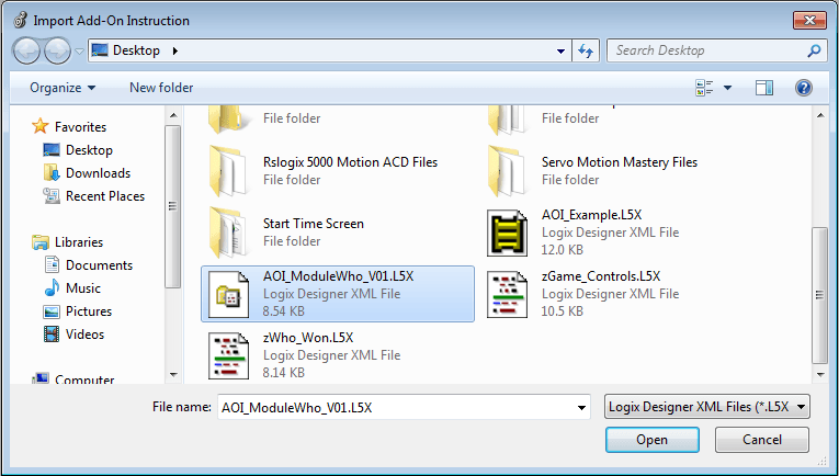
Right-click the Add-On Instruction folder then select “Import Add-On Instruction”

This will open up a folder that you can point to the place that you have the Add-On instruction that you want to import. In the case of what we are doing in this document, the name of the instruction is “AOI_ModuleWho_V01.L5X”.
Keep in mind that this file will be a .L5X file type.
When you point to the location that you have the instruction then select it & press the “Open” button.
Next, the import configuration tab will appear, if there is no edits to be made then all you have to do is to click the “Ok” button.
Note: At this point, there are limited things to be changed even if a change is to be made so it is best to wait until after import unless changing tag names through Find/Replace.

After you have clicked “Ok” then the process will finish.
Then the new Add-On instruction will be added to your program in the Add-On Instruction folder as shown below.

Programming In Studio 5000 Using The Add-On Instruction
Now it’s time to use the instruction.
The Add-On instruction that we are using here has the ability to detect the firmware of the I/O of any one model that is used in the program. Which is located in the root I/O tree.

We are now past the import stage of the Add-On instruction, for a recap, we have imported the “AOI_ModuleWho_V01.L5X” instruction which read the firmware of any module that you have in your I/O tree of your program after you use.
With that said, let’s start the logic editing.
Starting with adding a new rung in the desired routine that you want to add the new controls to, add a new rung then navigate to the top of the instruction bar element group Add-On section as shown below.

Installing the AOI in a rung
Once you add the new Add-On instruction to the rung then it should look as it does in the image below & once it does then we will start adding the proper tags to the AOI_ModuleWho_V01 instruction.
To quickly go through the tag structure of this instruction we have a list of the data types & structure, however, I would like to note that these data types auto-format when you make them.

About the Tags of the AOI
This list is to better describe the tag structure.
- AOI_ModuleWho_V01 is the main tag name for that instance of the instruction being used.
- IO_ModRef is a drop-down to select the module from your I/O tree that you want to use.
- Major_Firmware is populated after the instruction is active for the module’s major revision.
- Minor_Firmware is populated after the instruction is active for the module’s minor revision.
- MSG_Module_Who is a message block data type to read from the I/O Module.
- MSG_Module_Who_Dest is the data from the Module which is a data type of SINT[100]
With the existing listing above we can see that the proper data type for the tag being used with this Add-On instruction will be selected when you create the tag in the actual instruction.
Naming The Tags
Starting off we need to make a tag for the actual AOI & in the instance of this example, we are going to detect the firmware of a Powerflex 755 so we just named the tag Powerflex_755FW.
The reason is to an easy example tag name but we could have named it anything we wanted so please don’t think it has to be one tag name or another. Standard control Logix tagging usages.

After we name the AOI then we need to select the device that we want to monitor from the IO tree of the processor. A drop-down will appear when you press the IO_Module feature of this AOI so all you have to do is point to the device you want to use.
As shown below, we are going to monitor the Powerflex 755 firmware.
Add the Device To Monitor

The next tag we are going to make is for the MSG_Module_Who_Dest so we will skip over the MSG_Module_Who tag because we are going to use the MSG_Module_Who_Dest inside the message instruction of the MSG_Module_Who tag.
In this case, we made a tag called “WhoDest_755Data” which is shown below.
Adding The Message Data Tag
This tag was named that way just for example purposes so feel free to name the tag anything you would like.

Adding The Message Instruction Tag in the AOI
The final one that we need to make now is the MSG_Module_Who which is the message instruction that communicates to the IO module.
We have a special setup for that so please do not skip through this or you will create more work for yourself later.
Make a tag for the MSG_Module_Who section of the AOI but this time we are going to check the box on the bottom of the making the tag to open the message configuration section.
As shown in the example below.

As you can see, we name our tag “Get_PF755Who_MSG”.
Configuring The Message

Two things need to be changed on this first screen, the Service Type & the Destination Element.
The Service Type is to be set to “Device Who” & the Destination Type is to be set to the tag that you made for the WhoDest_755Data section of this AOI.
In our case, our tag name was “WhoDest_755Data”.
Note: we aren’t done just yet so do not close the message setup, we need to navigate to the communication tab of the message block & point the message to the device it is supposed to read.
As shown below.

After you have pointed the communication path to the device the AOI will be using then press the “Ok” button then the “Apply” button.
You can now close the message setup block, it is configured.
Adding The Data Collection Bit For The AOI
We now can finish the first part of the logic to do the first round of testing, add an XIC in front of the Add-On instruction so that it will only trigger once plus there is a special tag we have to use for the data to transmit properly.

Drag the Add-On instruction tag name over from the AOI to the XIC bit then use the drop-down to pick the .CMD_Module_Who bit, this bit is the one used in the Add-On instruction logic to populate the data.

Now download the PLC code & test.

To test the AOI, all you have to do is toggle the XIC bit we added.
Then it will read the data from the device & pull the firmware into the major & minor revisions.
Testing The AOI Instruction

There probably is a question by now of why we are using the .CMD_Module_Who bit from this Add-On instruction. The reason is because this tag is used directly in the Add-On instruction’s logic to transfer the data to the firmware tags so they will be displayed in the logic.
This populates the Major & minor firmware tags on the AOI just as shown below.

We can still continue to add on to this logic by adding a branch then two move instructions to populate two other tags which can be used anywhere you would like. To give a couple of examples, HMI system & different routines or even produced & consumed data.
Let’s add an example to show you.

Now we can add two tags to fit the data types of the Major & Minor firmware tags from the Add-On instruction. The data type of these two tags can be a DINT.

After the two tags are added to the MOV instructions then all we have to do is to test the AOI again using the .Cmd_Module_Who bit that we have in the XIC instruction.
This will allow the AOI to scan again then it will also load the Major & Minor firmware in the two new tags which in the example we did, we indicated them for an HMI readout.
This example was done in Studio 5000 version 30 & has been done in Rslogix 5000 version 20 so we thought we would verify that it works in Studio 5000 version 32 & it does.
Works just fine so feel free to use this in your processes.

Resources
Here is the download for the Add-On Instruction.
Download Here:
AOI_ModuleWho_V01.L5X – Install PDF & Download
Learn More About Add-On Instructions Here
More PLC Topics
RSLogix 5000 Section
-
RSLogix 5000 Add-On Instructions
-
How to Capture Allen Bradley Processor Faults
-
RSlogix 5000 Structured Text
-
RSlogix 5000 PID Tuning
-
Studio 5000 Indirect Addressing
-
User-Defined Data Types For Motion Applications
-
Allen Bradley PLC Servos Controls
-
Controlling Servo Motion With SFC Programming
-
Connecting a 1203-USB to A Kinetix 6000
-
Servo Motion Mastery Training
-
Advanced Servo Motion Mastery Training
-
Allen Bradley PLC Training
-
Ladder Logic
PLC Controls Section
RSLogix 5000 Add-On Instructions
How to Capture Allen Bradley Processor Faults
Studio 5000 Indirect Addressing
User-Defined Data Types For Motion
Allen Bradley PLC Servos Controls
Servo Motion With SFC Programming
Connect a 1203-USB to Kinetix 6000
Advanced Servo Motion Mastery PLC Training