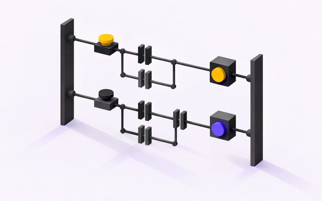
Motor control ladder logic is a rung of contacts and a coil that decides when a motor starter energizes. The core pattern is a normally open Start input, a normally closed Stop input, an overload input, and a seal-in contact from the motor output that keeps the rung true after Start is released. Every larger motor program, from a conveyor to a reversing drive, grows from that rung. This guide builds it step by step, adds forward-reverse interlocks, covers the U.S. safety rules that apply when you test it, and gives you a routine for when the motor will not start or will not stop.
TL;DR
- A start/stop rung is Start (normally open) in parallel with the output’s own seal-in contact, in series with Stop and overload contacts, ending in the motor coil.
- Wire Stop and overload as normally closed devices so a broken wire stops the motor instead of disabling the stop.
- Reversing starters need interlocks, in the program and in the wiring, so forward and reverse can never energize together.
- When a motor misbehaves, work from the output coil backward: coil, seal-in, Stop, overload, Start, then the field wiring.
- De-energize, lock out and verify zero energy before you touch power wiring.
Table of Contents
- Where motor control ladder logic comes from
- The symbols you need
- The start/stop rung with seal-in
- Forward-reverse motor control
- Building a good motor rung: practical habits
- Safety and U.S. requirements when you test motor controls
- Troubleshooting: the motor will not start or will not stop
- Our perspective on learning motor control
- Practice with us
- FAQ
- Sources
Where motor control ladder logic comes from
Ladder logic is the PLC version of relay control. Relay ladder circuits are the precursor to PLC ladder logic: two vertical power rails, horizontal rungs, and contacts and coils on each rung. Series contacts behave like AND, parallel contacts like OR, and a coil is the output. In a PLC, a microprocessor does the work that relays used to do.
The language was also designed to feel natural to electricians who already read relay schematics. That is why motor control is the best place to learn it. If you can read a hardwired start/stop station, you can read the PLC rung that replaces it.
A rung is read left to right and top to bottom. According to a university text on ladder and function block diagrams, each rung starts with one or more input contacts and ends with at least one output coil. If you are new to reading rungs, our walkthrough on reading PLC ladder logic covers the basics with a supporting video.
The symbols you need
For a motor rung you need only three instruction types. In Allen-Bradley software they are named like this:
| Symbol | Allen-Bradley name | What it does |
|---|---|---|
| Normally open contact | XIC (examine if closed) | Passes power when its bit is 1 |
| Normally closed contact | XIO (examine if open) | Passes power when its bit is 0 |
| Output coil | OTE (output energize) | Turns on when a complete path of power reaches it |
The names XIC, XIO and OTE are standard in ladder diagram programming. Other brands use different labels but the same logic.
One point trips up almost every beginner: the contact type in the program depends on the state of the bit, not on the label of the physical button. A normally open contact is true when its bit is 1, and a normally closed contact is true when its bit is 0, as one ladder logic explainer puts it. A normally closed Stop button wired to an input reads 1 while healthy, so you examine it with an XIC. Hold on to that and most start/stop confusion disappears.
The start/stop rung with seal-in
Here is the standard example, using the addresses from a widely used three-phase motor tutorial:
- I0.0: Start pushbutton, normally open
- I0.1: Stop pushbutton, normally closed
- I0.2: Overload contacts, normally closed
- Q0.0: Output to the motor starter coil
The rung, in text form:
|--+--[ I0.0 Start ]--+--[ I0.1 Stop ]--[ I0.2 OL ]--( Q0.0 Motor )--|
   |                  |
   +--[ Q0.0 Seal ]---+
How it runs
- You press Start. I0.0 closes, the Stop and overload inputs are already 1, and Q0.0 energizes the starter.
- On the next scan, the normally open Q0.0 contact closes. It sits in parallel with Start.
- You release Start. The seal-in contact still passes power, so the motor keeps running.
- You press Stop. The Stop input drops to 0, its contact opens, and Q0.0 de-energizes. The seal-in contact opens with it.
The tutorial describes exactly this sequence: the Q0.0 contact holds the output on after Start is released, and pressing Stop breaks the path.
The reason seal-in works is simple. It replaces a momentary Start-only path with an OR-style holding path: once the output is on, its own auxiliary contact keeps the rung true, so the start moment is no longer needed.
Why Stop and overload are normally closed
A normally closed Stop is the fail-safe choice. A start/stop programming guide notes that if the wire breaks or power is lost, the motor stops immediately. The same logic applies to the overload contacts. A normally open Stop would fail silently: a cut wire would leave you with a button that does nothing.
This three-wire pattern, with NO Start, NC Stop and overload contacts in series, is the same one used in hardwired motor control. If you want to see the same idea in Studio 5000 with a conveyor, try our Allen-Bradley ladder logic example.
Seal-in with an output bit versus a real feedback contact
The simplest program seals in on the output coil itself, as above. That tells you the PLC commanded the motor, not that the starter pulled in. Many plants wire an auxiliary contact from the contactor back to a PLC input and seal in on that, or use it for a run-feedback fault. Both are valid. Choose by what the machine needs to know. If an operator must be told the starter failed to close, you need the feedback input.
Forward-reverse motor control
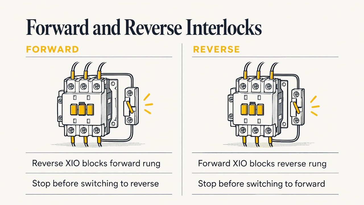
A reversing starter uses two contactors, one for each direction, which swap two of the three motor leads. If both close at once, the result is a short across the motor lines. An electrical-interlock lab manual explains that interlocking forces one contactor to drop out before the other can energize.
In ladder logic, build two start/stop rungs, one for forward and one for reverse, and add an interlock to each:
|--+--[ Fwd Start ]--+--[ Stop ]--[ OL ]--[/ Rev Out ]--( Fwd Out )--|
   +--[ Fwd Out ]----+

|--+--[ Rev Start ]--+--[ Stop ]--[ OL ]--[/ Fwd Out ]--( Rev Out )--|
   +--[ Rev Out ]----+
Each rung includes an XIO on the opposite direction’s output. While forward is on, the reverse rung cannot complete, and vice versa. The operator must press Stop before changing direction.
Do both: program and wiring
Software interlocks are not enough on their own. Electrical interlocking uses normally closed auxiliary contacts on one contactor in series with the coil of the other direction’s contactor, and the reverse. This protects you if a contactor welds shut or a logic edit goes wrong. Keep the hardware interlock and the program interlock together.
The same rule applies when the PLC drives a VFD. A PowerFlex 4 forward-reverse example uses separate rungs for the FWD and REV outputs and states that interlock logic is required so both outputs are never on together. If you are working with drives, our Powerflex 525 course is built for that next step.
Building a good motor rung: practical habits
- Put the output coil once. Writing the same coil on two rungs means the last one scanned wins, and troubleshooting turns into a guessing game.
- Name your tags by function. Motor1_Start, Motor1_Stop_OK and Motor1_Run read better than B3:0/0.
- Keep permissives in series. Guards closed, no fault, and auto mode all belong in the same series path as Stop and overload.
- Do not rely on the PLC for emergency stop. Hardware must remove power to the starter coil regardless of what the program does.
- Add a run timer or feedback fault when the process needs to know the motor failed to start.
The beginner ladder logic example on our site shows how these rungs fit into a complete small program.
Safety and U.S. requirements when you test motor controls
Motor control work puts you next to live power and moving machinery. A few rules matter most.
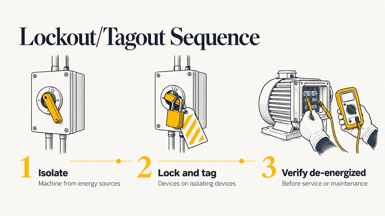
Lockout/tagout. OSHA’s control of hazardous energy guide describes an energy-control program: isolate the machine from its energy sources, apply lockout/tagout devices to the isolating devices, and verify de-energization before service or maintenance begins. Follow your site’s written procedure, and have a qualified electrician do any work on power conductors.
Bench and panel standards. A bench build guide points to NFPA 79-2024 for industrial machinery wiring, NFPA 70E-2024 for arc-flash boundaries and lockout before energizing, UL 508A for panels plugged into plant power, and OSHA 29 CFR 1910.212 for machine guarding.
Control circuit and overload rules. Under the NEC, if one conductor of a motor control circuit is grounded, section 430.74 requires that a ground fault cannot start the motor or bypass shutdown devices. That is why Stop, Start and overload contacts belong in the ungrounded leg. The same guide covers NEC 430.32(A)(1), which sets overload protection at no more than 125% of nameplate full-load amps for continuous-duty motors with a service factor of 1.15 or more (or a marked temperature rise of 40°C or less), and 115% for others. NEC 430.37 calls for an overload unit in each of the three ungrounded conductors of a three-phase motor circuit. Confirm requirements against the code edition your jurisdiction has adopted.
Troubleshooting: the motor will not start or will not stop
Work from the output backward. Most motor faults are found in a few minutes if you follow the same order every time. Use the online view in your programming software so you can see which contacts are passing power.
Motor will not start
- Is the coil energized in the program? If the coil is on but the motor is not running, the problem is outside the logic: the output module, field wiring, the starter coil, control power or the overload relay itself.
- If the coil is off, find the first false contact on the rung. Read left to right. The first contact that is not passing power is your answer.
- Check Stop and overload inputs. These are normally closed devices, so a tripped overload, a mushroom button left latched, or a loose wire reads as 0 and blocks the rung. This is the most common cause.
- Check Start. Press it and watch the input bit. If the bit never changes, the fault is the button, wiring or input card, not the program.
- Check permissives. Guards, auto mode, interlocks and fault bits in the series path may be the real reason.
Motor starts but stops when you release Start
The seal-in is not holding. Look for a seal-in contact with the wrong address, a seal-in on a different output than the coil, or a contact in the parallel branch that sits behind a false instruction. Also check that the output coil is not written on another rung that turns it off.
Motor will not stop
- Watch the Stop input. If it reads 1 while the button is pressed, the wiring or input card is the problem. Check for a jumper someone left in.
- Check whether another rung or a force is holding the output on. Forces in particular can hide a problem.
- If the PLC output is off but the motor still runs, the starter contacts may be welded. Take it out of service and replace the contactor under lockout/tagout.
Forward-reverse problems
If one direction works and the other does not, check the opposite direction’s interlock contact first. A sticky auxiliary contact or a bit left on in the other rung blocks the rung exactly as it was designed to.
Whenever the next step means opening a panel or touching terminals, stop, lock out, and verify zero voltage first.
Our perspective on learning motor control
Motor control is where most technicians first feel PLC programming click. The rung is small enough to hold in your head, and the habits it teaches carry into every larger program: read the bit states, find the first false contact, and never trust a single safeguard.
We design our training around real-life examples and practical strategies because that is how people become confident on the plant floor. A student who has built a start/stop circuit in Studio 5000, watched it online, and then broken it on purpose to find the fault learns more in an afternoon than from a page of symbols.
Our content covers software such as RSLogix 500, RSLogix 5000, Studio 5000 and FactoryTalk View Studio, and it is made for all skill levels. Our aim is to keep training clear, structured and affordable, so engineers, maintenance professionals and students can build skills without a large bill.
the author
Practice with us
If you want to move from reading motor rungs to writing and troubleshooting them, our Allen Bradley PLC training walks through ladder logic in Studio 5000 with practical examples, and the course page also lists our Powerflex 525 and FactoryTalk View ME courses.

If you have a specific motor program or a fault you cannot find, a live session is faster. Our 90-minute PLC coaching session is $97 per session, and online PLC coaching starts from $67 per session. For ongoing learning, the Yearly PLC Training Membership is $192 per year.
FAQ
What is a seal-in contact in motor control ladder logic?
It is a normally open contact from the motor output, placed in parallel with the Start button. Once the output turns on, the contact closes and keeps the rung true after you release Start. Pressing Stop opens the series path and drops the output.
Why is the Stop button wired normally closed?
A normally closed Stop is fail-safe. If the wire breaks or power is lost, the input reads 0 and the motor stops. A normally open Stop would leave you with a dead button and no warning.
How do you stop forward and reverse from energizing together?
Use interlocks in both the program and the wiring. In the program, put a normally closed contact of each direction’s output in the other direction’s rung. In the wiring, use normally closed auxiliary contacts of each contactor in series with the other’s coil.
Why does the overload input matter in the rung?
The overload contacts open when the overload relay trips, which drops the rung and stops the motor. Wired normally closed in series, they also stop the motor if the wire is cut. After a trip, find the cause before you reset it.
Where should I start if the motor will not run?
Open the rung online and find the first contact that is not passing power. Check the Stop and overload inputs first, since normally closed devices fail open. If the coil is on but the motor is not, look at the output, wiring and starter.
Sources
- Relay Circuits and Ladder Diagrams
- Ladder Diagram (LD) Programming Contacts and Coils
- Ladder and FBD, Chapter 11 (W. Bolton)
- Motor start/stop seal-in circuit
- What Is Ladder Logic? How to Read It
- Basic PLC program for control of a three-phase AC motor
- PLC start/stop circuit ladder logic programming guide
- Motor Control: Forward-Reverse Control
- Forward/Reverse Control Circuits
- Configuring PowerFlex 4 VFD Forward Reverse Control with PLC
- Control of Hazardous Energy (OSHA 3120)
- PLC Training Bench Build Guide
- Wiring a 3-Phase Motor Starter