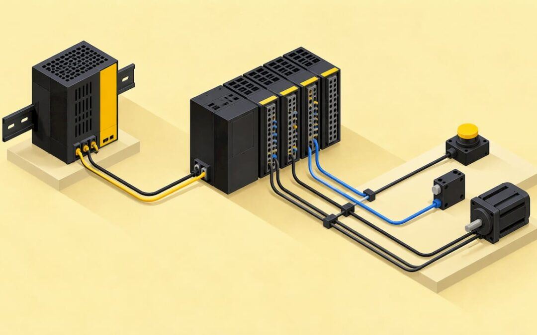
PLC wiring comes down to three circuits: power to the controller, field devices wired to input terminals, and output terminals wired to the loads they switch. Get the power, the commons and the output type right, and prove each point one at a time before the machine moves. This guide walks through each circuit in the order you would build it, with the mistakes that cause most first-day failures. If you want someone to check your wiring against your own drawings, our online PLC coaching is built for exactly that.
TL;DR
- A PLC panel needs supply power, overcurrent protection, a disconnect or e-stop circuit, terminals and a ground path before any I/O is wired.
- Every input and output circuit needs a current path out and a return path back, usually through a shared COM terminal.
- Wire every point on a common the same way: all sinking or all sourcing. Never put AC on a DC sink/source module.
- Relay outputs switch AC or DC loads. Transistor outputs switch DC loads only and are polarity sensitive.
- Test inputs by actuating each device and watching its LED. Test outputs one at a time with motion devices disconnected.
Table of Contents
- What a PLC wiring setup contains
- The idea behind every I/O circuit: current in, current out
- Wiring PLC inputs
- Wiring PLC outputs
- Safe testing before you run the machine
- Troubleshooting patterns worth knowing
- What a good PLC wiring course should cover
- Our perspective
- Get help applying this to your panel
- FAQ
- Sources
What a PLC wiring setup contains
A wiring diagram shows physical connections: terminals, devices and wire numbers. The PLC program explains when and why the controller acts. You need both to understand how a machine behaves, and wiring is the half that fails first on a new build.
According to Electrical Engineering Portal’s panel design guide, an industrial PLC panel should include at least:
- a transformer to step down the AC supply voltage
- power contacts that let an e-stop enable or disable machine power
- terminals to connect devices
- fuses or circuit breakers for overcurrent protection
- grounding to give fault current a path
- an enclosure to protect equipment and people
The same source notes that 110 V AC is common in North America, so many U.S. panels feed the PLC power supply from a control transformer or a 120 V branch circuit. Check the voltage printed on your CPU or power supply label before you energize anything.
Power and grounding
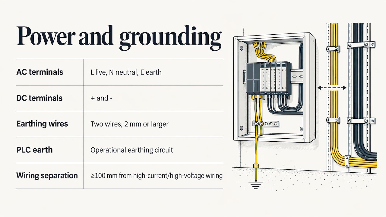
AC supply terminals are marked L (live), N (neutral) and E (earth). DC supplies use + and -. PDF Supply’s wiring guide describes earthing with two wires of 2 mm or larger, with the PLC earth going to the operational earthing circuit, and keeping input and output wiring at least 100 mm away from large-current and high-voltage wiring.
That separation matters in practice. A 24 V DC proximity sensor cable bundled with a motor lead will pick up noise and produce phantom inputs that look like a programming bug.
Protection also deserves a deliberate design, not an afterthought. For a look at how power distribution and electrical protection are handled on machine panels, see this piece on electrical protection for machine panels.
How to read the diagram
Start at the power source and trace it to each module, then out to each field device. Look for wire numbers, terminal labels, contact type (normally open or normally closed) and the input or output channel each device lands on. Ladder-style schematics have two rails, with the left side of each rung holding the conditions and the right side the controlled element. If you are new to that layout, our guide to reading PLC ladder logic shows how the schematic and the program line up.
The idea behind every I/O circuit: current in, current out
AutomationDirect’s sinking and sourcing guide puts it simply: every I/O circuit needs an incoming current path and a return path, and groups of points commonly share one COM terminal. Most wiring mistakes are a missing return path or a COM wired to the wrong side of the supply.
The same document makes two rules worth memorizing:
- Sinking and sourcing terms apply to DC circuits. Never use AC power on DC sink/source I/O.
- All points that share a common should be wired consistently, all sinking or all sourcing.
Wiring PLC inputs
An input module senses whether a voltage is present. Your job is to give each field device a path that either supplies or returns current through the input point.
Digital inputs
Push buttons, limit switches, selector switches and proximity sensors all connect the same basic way:
- Choose the supply: 24 V DC for most modern DC input cards, or the AC voltage that matches an AC input card.
- Wire one side of the supply to the field device.
- Wire the other side of the device to the input terminal.
- Wire the module’s COM to the supply so the circuit returns.
With a DC input card, the COM choice sets the type. If COM goes to the supply negative, the input is sourcing current from the device, so you wire switches to +24 V and then to the point. If COM goes to the supply positive, the input is sinking and the switch connects the point to supply negative. Two-wire dry contacts work either way. Three-wire sensors are where it matters: an NPN sensor needs a sourcing input, and a PNP sensor needs a sinking input, so match the sensor to the card before you land wires.
A common beginner error is wiring a stop button as normally open. Use a normally closed contact for stops and safety-related inputs so a broken wire stops the machine instead of hiding the fault.
Analog inputs
Analog signals carry a measurement, not an on/off state. The two you will meet most are 4-20 mA and 0-10 V. For 0-10 V, signal positive goes to AI+ and signal common goes to AI-. The channel must then be configured in software as voltage or current to match the device.
For 4-20 mA transmitters, know how many wires you have:
| Transmitter | How it is powered | Wiring approach |
|---|---|---|
| Two-wire, loop powered | From the loop supply | DC supply to transmitter, transmitter to PLC current input, return to supply |
| Three-wire | Separate power conductor | Power, common and signal conductors, each landed separately |
| Four-wire, self powered | Its own supply | Do not add loop power |
Use shielded twisted-pair cable for analog runs and ground the shield at one end only, usually at the panel, so you do not create a ground loop.
Wiring PLC outputs
Outputs are where wiring turns into motion, heat and light, so choose the output type before you pick the load.
Relay vs. transistor outputs
| Feature | Relay output | Transistor output |
|---|---|---|
| Load type | AC or DC | DC only |
| Polarity | Not sensitive | Must be correct |
| Switching | Isolated mechanical contacts | Solid state |
| Typical use | Contactors, pilot lamps, mixed voltages | Fast DC loads, small solenoids, indicator lights |
As Control.com’s source and sink wiring guide explains, most output modules are the sourcing type: each terminal supplies 24 V to the load when energized. In the less common sinking case, the terminal provides the path back to the negative supply. A sinking output cannot be checked with the load disconnected, because a voltmeter reads 0 V whether or not the point is on. Always measure with the load connected.
Driving loads bigger than the output card
PLC digital outputs typically deliver 24 V DC at about 0.5 to 2 A. For a 110 V AC solenoid valve or a contactor, put an interposing relay between them. Industrial Monitor Direct’s wiring guide describes the path: the DO terminal drives the relay coil on the 24 V DC circuit, and the relay contact switches the valve on the 110 V AC circuit. It uses a 2 A fuse on the coil circuit and a 5 A fuse on the AC valve circuit. Your fuse sizes depend on your loads, so size them from the device nameplates.
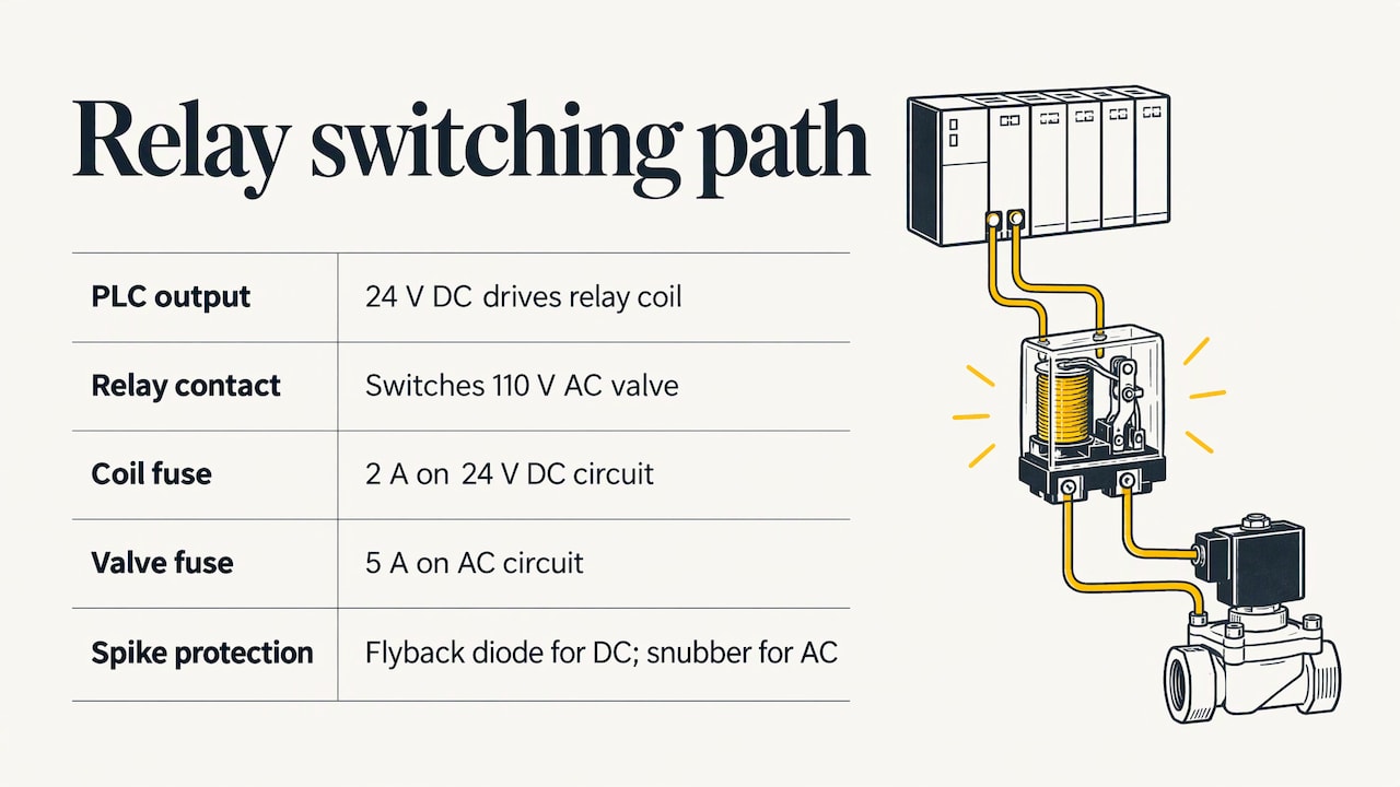
Also fit a flyback diode across DC relay coils and an RC snubber or surge suppressor across AC coils. Switching inductive loads creates voltage spikes that shorten contact life and can reset the controller.
Safe testing before you run the machine
Wiring is only done when it has been proven point by point. The IDC Online PLC startup document lays out a method that still holds up.
Static input check
- Put the controller in a mode that inhibits automatic operation.
- Apply power to the controller and input devices.
- Actuate each input device by hand.
- Watch the matching LED on the input module, and confirm it is the right address.
An LED that lights on the wrong point tells you a wire landed on a neighboring terminal. An LED that never lights usually means a missing common or a wrong sink/source match.
Static output check
- Locally disconnect every output device that causes mechanical motion, such as motors and solenoids.
- Apply power to the controller and I/O devices.
- Verify that the emergency stop circuit removes power when activated.
- Test each output one at a time using the forcing function or a dummy rung in the program.
Force only one point at a time, and release every force when you finish. Leftover forces are a classic source of machines that behave strangely weeks later.
Safety when the panel is open
De-energize before you work on wiring, and apply lockout/tagout. In November 2024 OSHA released updated arc flash guidance that, according to Voltage Lab’s summary, endorses NFPA 70E and stresses de-energizing, lockout/tagout and verification of the de-energized state. If a task has to be done live, such as measuring a voltage, follow your employer’s electrical safety program and use qualified personnel with the right PPE. For panel construction and field wiring on a new installation, your electrical inspector or licensed electrician decides what applies under the National Electrical Code.
Troubleshooting patterns worth knowing
| Symptom | Likely wiring cause | First check |
|---|---|---|
| Input LED never lights | Missing or wrong common, dead supply | Measure supply at the module terminals |
| Input LED lights with device off | Leakage current, noise, wrong NO/NC contact | Check contact type and cable routing |
| Output LED on, load off | Open load wiring, blown fuse, wrong polarity | Measure at the load with it connected |
| Output LED off when forced | Forces disabled, wrong address, faulted module | Confirm the address against the drawing |
| Analog reading stuck at zero or full scale | Channel set to wrong signal type, open loop | Verify configuration matches the transmitter |
Work from the supply outward. Prove the 24 V rail first, then the common, then the device, then the program address. Wiring faults are usually found in that order, and the program is rarely the first thing to blame.
What a good PLC wiring course should cover
If you are choosing training, look for these skills, because they are what a technician actually does on a machine:
- reading a panel schematic and finding a device from its wire number
- sinking and sourcing, including matching NPN and PNP sensors to a card
- wiring analog loops and setting the channel type
- choosing relay or transistor outputs and adding interposing relays
- measuring with a multimeter on a live, locked-out and de-energized circuit, as appropriate
- using forces and test rungs to verify each point
- tying wiring to the program: the address on the drawing must match the tag in the logic
That last point is the one many wiring-only resources skip. A technician who understands both the terminals and the ladder logic troubleshoots in minutes what others chase for hours. Our PLC motor control guide connects the wiring, the ladder logic and the safety circuit for a motor starter, and PLC instructions in use shows how the logic side responds to the inputs you just wired.
Our perspective
Most people learn wiring from a diagram and programming from a screen, and never see the two meet. The first time the signal does not arrive, they have no method for finding out which side is at fault.
We teach PLC and HMI work with real-life examples and hands-on strategies, using industry-standard software such as RSLogix 500, RSLogix 5000, Studio 5000 and FactoryTalk View Studio. Our training is designed to be practical, cost-effective and accessible for all skill levels.
The habit that serves you best is simple: name the address on the drawing, find the same address in the program, and prove the point in the field. Do that for every I/O point and wiring stops being guesswork.
the author
Get help applying this to your panel
Reading about commons and relays is one thing. Checking your own drawing is faster with someone who has done it on real machines. Our 90-Minute PLC Coaching Session is $97 per session, and Online PLC Coaching starts from $67 per session. If you want structured learning, the Yearly PLC Training Membership is $192 per year, and our Allen Bradley PLC training covers the programming side that goes with the wiring.

Teams that need a machine programmed can also use our PLC programming services at $140 per hour.
FAQ
What is the difference between sinking and sourcing?
A sourcing terminal supplies current to the load, and a sinking terminal provides the path back to the negative supply. The terms apply to DC circuits only. Wire every point sharing a common the same way, and match NPN and PNP sensors to the correct input type.
Can a PLC output drive a 110 V solenoid directly?
Typically no. Digital outputs usually deliver 24 V DC at around 0.5 to 2 A, so a 110 V AC solenoid valve is switched through an interposing relay or contactor. The PLC output drives the relay coil, and the relay contact switches the AC load, each circuit with its own fuse.
Do I need a relay or a transistor output?
Choose a relay output when you need to switch AC or DC loads or isolate circuits. Choose a transistor output for DC loads where correct polarity is wired and switching is frequent. Check the module’s rated current per point and per common before you load it.
How do I test PLC wiring before starting the machine?
With automatic operation inhibited, actuate each input and watch its LED. For outputs, disconnect motion devices, confirm the e-stop removes power, then force each output one at a time. Release all forces when you finish.
Sources
- Basic electrical design of a PLC panel, Electrical Engineering Portal
- How to Read a PLC Wiring Diagram, PDF Supply
- Sinking and Sourcing Concepts, AutomationDirect
- Guide to Source and Sink Controller Wiring, Control.com
- PLC DI/DO Wiring Guide, Industrial Monitor Direct
- PLC Startup, IDC Online
- NFPA 70E 2026 Updates, Voltage Lab
- Electrical protection for machine panels