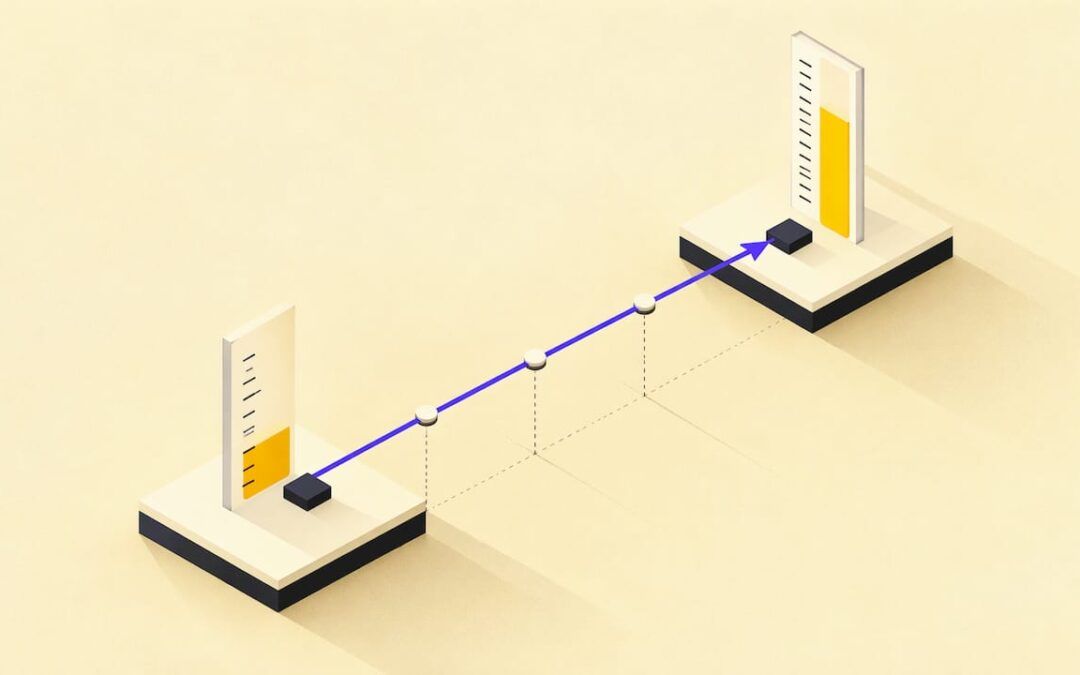
PLC analog input scaling is one linear equation that turns the raw count an analog card reports (for example 9,830) into the engineering unit your process cares about (for example 50 psi). You need two known points, the raw counts at the bottom and top of the signal and the engineering values they stand for, and you apply them as a straight line. The rest of this guide shows the formula, three worked examples, the out-of-range traps and the symptoms that point to a scaling mistake. If you would rather build this on real hardware with an instructor, our 90-Minute PLC Coaching Session is $97 per session.
TL;DR
- Scaling maps a raw input range to an engineering range with a straight line: EU = EU_min + (Raw − Raw_min) × (EU_max − EU_min) ÷ (Raw_max − Raw_min).
- Raw counts are not universal. An Allen-Bradley SLC 500 analog card puts 4–20 mA at 3,277–16,384 counts, while Siemens S7-1200 modules use 0–27,648 for the rated current range.
- Use floating-point (REAL) math. An integer result truncates and often reads 0.
- Clamp the value or watch the status bits, because linear scaling keeps going past the range when a wire breaks or a sensor overranges.
- Verify with a loop calibrator at 4, 12 and 20 mA before you trust the number on the HMI.
Table of Contents
- What PLC analog input scaling does
- The scaling formula
- How to scale an analog input, step by step
- Worked example 1: Allen-Bradley 4–20 mA pressure
- Worked example 2: Siemens S7-1200
- Worked example 3: a 13-bit unit with a decimal place
- Raw counts differ by platform
- Out-of-range values and clamping
- Troubleshooting a wrong scaled value
- Our perspective
- Build this on real hardware with us
- FAQ
- Sources
What PLC analog input scaling does
An analog input card measures a voltage or current and hands the controller an integer. That integer means nothing to an operator. Siemens describes the job as normalizing the analog value to a range of 0.0 to 1.0 and then scaling it to the minimum and maximum engineering values it represents, such as volume, temperature or weight.
Two things sit on either side of the scaling step:
- The signal. For instrumentation, the standard analog signaling range is 4–20 mA, as set out in ANSI/ISA-50.00.01. The 4 mA floor is called a live zero: a reading of 0 mA tells you the loop is broken rather than the process being at zero.
- The card. The card converts the signal to counts. How many counts, and where 4 mA lands, depends on the manufacturer and the module.
Scaling is the bridge between them. Do it once, in one place, and every alarm, trend and display downstream works in real units. Alarm thresholds written against scaled values are readable by anyone on the plant floor, where a threshold written against a raw count is not.
The scaling formula
The general linear conversion is:
EU = EU_min + (Raw − Raw_min) × (EU_max − EU_min) ÷ (Raw_max − Raw_min)
Rockwell Automation describes the same two-point relationship: the low signal corresponds to the low engineering value, the high signal to the high engineering value, and everything between is linear. Siemens gives the same equation in its S7-1200 manual with a worked case: an engineering range of 50 to 100 and an input range of 0 to 27,648 becomes 50 + Input × (100 − 50) ÷ 27,648.
Four terms, in plain words:
| Term | Meaning | Where you find it |
|---|---|---|
| Raw | The integer the card reports right now | The input tag in your program |
| Raw_min, Raw_max | Counts at the bottom and top of the signal | The module manual for the range you configured |
| EU_min, EU_max | The process values at 4 mA and 20 mA | The transmitter’s calibrated range, often on its nameplate |
| EU | The result, in psi, °F, gallons per minute and so on | Your scaled output tag |
Omron adds a useful point: it is convenient to use the full input range as your two points, but any two known points of input versus output define the line. That matters when the sensor only uses part of the module’s range.
How to scale an analog input, step by step
- Read the transmitter range. Write down what 4 mA and 20 mA mean. A pressure transmitter ranged 0–100 psi means 4 mA = 0 psi and 20 mA = 100 psi.
- Find the raw counts for your module. Look in the module manual or the configuration screen for the counts at the bottom and top of the range you selected. This is where most mistakes begin, because the same signal gives different counts on different hardware.
- Choose a data type. Put the result in a REAL (floating-point) tag. Control.com’s Siemens tutorial notes that an integer output in the scale command truncates the result to 0.
- Build the math. Use a compute instruction with the formula, a dedicated scale instruction, or a normalize-then-scale pair. They all do the same arithmetic.
- Handle out-of-range values. Decide what the program does when the raw value is below Raw_min or above Raw_max. More on that below.
- Test at three points. Inject 4, 12 and 20 mA with a loop calibrator and confirm the scaled value reads the bottom, middle and top of the range.
- Document the tag. Put the engineering range and units in the tag description so the next person does not rebuild the math.
If you want the instruction side of this in Logix, our walkthrough of PLC instructions in use shows how compute and move instructions are applied in ladder logic.
Worked example 1: Allen-Bradley 4–20 mA pressure
The ISA example for an Allen-Bradley SLC 500 analog card puts 4 mA at 3,277 counts and 20 mA at 16,384 counts. The span is 16,384 − 3,277 = 13,107 counts. The same source gives the equation for a 0–700 GPM flow range as EU = (700 ÷ 13,107) × Raw − 175.
Apply that pattern to a 0–100 psi transmitter:
- Slope: 100 ÷ 13,107 = 0.007629 psi per count
- Offset: 0.007629 × 3,277 = 25.0 psi
- EU = 0.007629 × Raw − 25.0
Check the middle: 12 mA is half way, so the raw value is about 9,830. Then 0.007629 × 9,830 = 75.0, and 75.0 − 25.0 = 50.0 psi. That is correct for a signal half way up the range.
The offset is the part people forget. If you only multiply by the slope, the bottom of the range reads 25 psi when the process is at zero. That is the most common mistake on 4–20 mA inputs, because the live zero means the raw count at the bottom is not zero.
In Studio 5000 or RSLogix 5000 you can do the same math in a compute (CPT) instruction. In RSLogix 500 you would use a compute instruction as well. On many Logix analog modules you can instead enter the low and high signal and low and high engineering points in the module configuration, and the module then returns data to the controller in engineering units, as Rockwell describes. Know which method a given project uses before you add scaling in code, or you will scale the value twice.
Worked example 2: Siemens S7-1200
Siemens general-purpose analog modules return integers where 0 to 27,648 represents the rated range for current, and −27,648 to 27,648 for voltage. Values outside that band indicate overflow or underflow. Control.com’s tutorial states that 10 V converts to 27,648.
With the channel configured for 4–20 mA, 4 mA is the bottom of the rated range (0 counts) and 20 mA is the top (27,648). Take a level transmitter ranged 0–10 m and a raw value of 20,000:
- Normalized: 20,000 ÷ 27,648 = 0.7234
- Scaled: 0 + 0.7234 × (10 − 0) = 7.23 m
Siemens’ two-step method is NORM_X, which produces a REAL between 0.0 and 1.0, followed by SCALE_X, which maps it to your engineering range. A single compute rung gives the same answer. Quick check points on a loop calibrator for a 4–20 mA channel: 4 mA reads 0, 12 mA reads 13,824 and 20 mA reads 27,648.
Two details save you time on this platform:
- Instruction status. According to the Siemens manual, SCALE_X sets ENO to FALSE if the result exceeds the valid range of the output data type or if MAX is not greater than MIN, and NORM_X sets ENO to TRUE when VALUE falls outside MIN to MAX. Out-of-range values can normalize below 0 or above 1. The instruction does not stop you; it keeps extrapolating.
- Range mismatch. If the channel is set to 0–20 mA while the transmitter is 4–20 mA, 4 mA arrives as roughly 5,530 counts (20 percent of 27,648), and your bottom reading is off by a fifth of span. Make the module configuration and the NORM_X minimum agree.
Worked example 3: a 13-bit unit with a decimal place
Some controllers report a smaller count range. AutomationDirect’s analog scaling appendix uses the form Units = A × (H − L) ÷ 8191 + L, where A is the analog value from 0 to 8191 and H and L are the high and low limits of the engineering range. For a 0.0–99.9 psi scale, a raw value of 4,047 gives 49.4 psi.
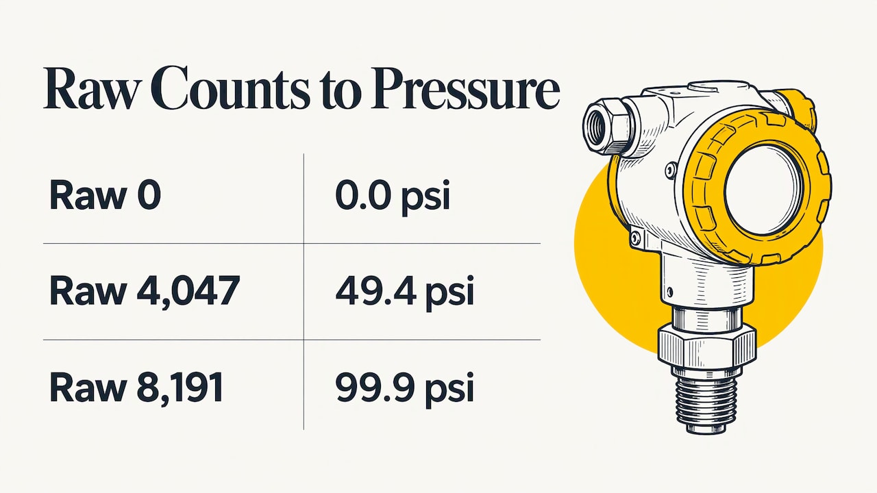
The same appendix shows a useful trick for integer-only math: multiply by 10 so that 49.4 psi is stored as 494, with the decimal place implied. You then divide by 10 for display. That keeps the precision when the platform does integer arithmetic, but on any controller with REAL support, scale directly to a REAL instead and skip the implied decimal.
Raw counts differ by platform
Do not carry counts from one project to the next. The same 4–20 mA signal lands on different integers depending on the card:
| Platform (example) | 4 mA | 20 mA | Source |
|---|---|---|---|
| Allen-Bradley SLC 500 analog card | 3,277 | 16,384 | ISA example |
| Siemens S7-1200 analog module | 0 | 27,648 | Siemens manual |
| Omron 4000-point unit | 0 | 4,000 | Omron knowledge base |
The Omron entry is the converted range its knowledge base cites for a 4,000-point resolution unit, typically 0–4000, with a temperature example mapping 0–4000 counts to −50 to +250 °C. Always confirm against the manual for your exact module and the range you configured, because many modules offer several input ranges and the counts change with each.
Out-of-range values and clamping
A healthy 4–20 mA loop stays between 4 and 20 mA. A real plant does not. Sensors overrange, wires break, and some modules report values a little beyond full scale. Because the scaling equation is a straight line, it will happily report a pressure of 112 percent of span or a negative level.
There are two sensible responses:
- Clamp. Limit the normalized value to 0.0–1.0 before scaling, so the engineering value never leaves its range. This suits displays and PID inputs where a wild number does damage.
- Flag. Compare the raw value against the low and high limits and set a bad-quality bit. A raw value well below the 4 mA count means a broken wire or lost power, and that is a fault, not a process value.
Use both together on critical loops: clamp the number the control logic uses and raise a fault alarm so the operator knows the instrument has a problem. Which fault limits you choose depends on the module’s documented over-range and under-range behavior.
Troubleshooting a wrong scaled value
When a reading is wrong, work from the signal inward. This table maps what you see to the usual cause.
| Symptom | Likely cause | Check |
|---|---|---|
| Bottom of range reads above zero (such as 25 psi) | Offset left out of the formula on a 4–20 mA signal | Compare the formula to the two-point equation |
| Scaled value always 0 | Integer output type truncating a fraction | Make the output tag a REAL |
| Reading stops at about 80 percent of span | Module set to 0–20 mA while the transmitter is 4–20 mA, or the reverse | Compare module range configuration to the loop |
| Large negative or very large raw number | Under-range (below 4 mA) or overflow (above about 20 mA) | Measure loop current with a meter |
| Value reads half of expected or double | Wrong Raw_max in the equation, such as a 32,767 guess instead of the module’s real full-scale count | Look up counts in the module manual |
| Neighbor channels drift or jump | Unused inputs left floating on certain Allen-Bradley modules | Check the module’s wiring instructions |
A reliable procedure for any of them:
- Put a calibrator or a known mA source on the loop and inject 4, 12 and 20 mA.
- Read the raw tag at each point. If the raw numbers are wrong, the problem is the card, the wiring or the configuration.
- If the raw numbers match the manual, check the scaled output. If it is wrong, the problem is your equation or data type.
- Confirm the engineering range against the transmitter nameplate, not against the drawing alone.
Scaling and calibration are different jobs. Calibration corrects the sensor and input so the signal and the counts agree with the real process. Scaling assigns engineering values to those counts. A well-scaled but uncalibrated loop still shows the wrong number, so when the raw counts check out and the reading is still off against a trusted gauge, look at the transmitter.
Once your scaled values are right, the next question is how to record them. Our guide to PLC logging covers capturing and storing data you can trust.
Our perspective
Most scaling problems we see in training sessions are not math problems. The formula is two points and a straight line. The trouble is that students copy a rung from one platform, where 4 mA is 3,277 counts, into another, where it is 0, and nobody checks the module range.
Our approach is to teach scaling as a habit, not a recipe: read the transmitter range, read the module manual, write the equation, test at 4, 12 and 20 mA, then document it. That sequence works on Allen-Bradley and Siemens alike, and it is the same sequence we practice with real examples in our courses and coaching.
We design our training to be practical, cost-effective and open to every skill level, so a student can build their first scaled input and a maintenance technician can chase a bad reading with the same method.
the author
Build this on real hardware with us
Reading the formula is easy. Getting it right on your own controller, with your own transmitter and your own module, is where a second pair of eyes saves hours. Our Allen Bradley PLC Training covers practical programming in RSLogix 500, RSLogix 5000 and Studio 5000. If you want to work through a specific scaling problem live, the 90-Minute PLC Coaching Session is $97 per session, and Online PLC Coaching starts from $67 per session. Our Yearly PLC Training Membership is $192 per year.

Teams that want everyone scaling and troubleshooting the same way can start from our PLC training courses and build a shared standard.
FAQ
How do I scale an analog signal in a PLC?
Find the raw counts at the bottom and top of your signal range and the engineering values they represent. Then apply EU = EU_min + (Raw − Raw_min) × (EU_max − EU_min) ÷ (Raw_max − Raw_min) in a REAL tag. Test at 4, 12 and 20 mA to confirm the result.
What is 4–20 mA scaling?
It maps a 4–20 mA loop signal onto a process range, so 4 mA is the low end and 20 mA the high end. On a 0–160 °C span, 12 mA is the midpoint and reads 80 °C. The nonzero floor lets the PLC tell a true zero from a broken loop.
Why does my scaled value read 0?
The most common cause is an integer output tag, which truncates the fractional result of the normalized value. Change the output to a REAL. If it still reads 0, check whether the raw input is 0, which points to a wire break or a wrong range configuration.
Do all PLCs use the same raw count range?
No. An Allen-Bradley SLC 500 analog card reports 3,277 to 16,384 counts for 4–20 mA, and Siemens S7-1200 modules use 0 to 27,648 for the rated range. Read the manual for your module and the range you configured before you write the equation.
Sources
- Processing of analog values, Siemens S7-1200 manual
- SIMATIC S7-1200 programmable controller documentation
- Scaling and the scaling equation, Rockwell Automation
- Scaling, Rockwell Automation analog modules
- Appendix B Analog I/O Scaling Examples, AutomationDirect
- How can I scale an analog input or output?, Omron
- Relating 4 to 20 mA Signals to Instrument Variables, Control.com
- Siemens TIA Portal and S7-1200 Tutorial 2: Analog Inputs, Control.com
- ISA50, Signal Compatibility of Electrical Instruments, ISA