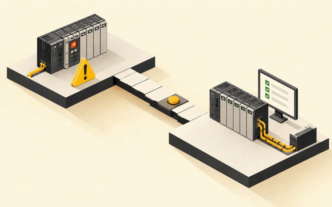
To troubleshoot an Allen-Bradley PLC, make the machine safe, write down the exact symptom, read the controller’s status indicators and fault code, then work outward: power and physical connections, I/O modules, network communications, and only then the logic. Most downtime comes from skipping that order and opening the program first. This guide walks through the sequence we teach, with the manufacturer’s own documentation as the reference for each step.
TL;DR
- Confirm safe conditions and plant procedures first, then record the symptom and what changed before touching anything.
- Read the controller LEDs and the fault code. A major fault halts logic execution, and the code tells you where to look.
- Rule out power, grounding, seating, cabling and IP settings before you suspect the program.
- Reset faults selectively and only after you understand the cause. Never clear everything blindly.
- Verify the repair: the I/O status indicator should be solid green and module fault codes should be clear.
Table of Contents
- Start with safety and the symptom
- Read the controller status first
- Check the physical layer before the logic
- When inputs or outputs are not responding
- When communications fail or you cannot go online
- Common faults: watchdog, lost modules and Program mode
- Reset a fault safely
- Verify the fix
- A quick symptom-to-first-check table
- Build the habit, not just the fix
- Perspective
- Get help with your own fault
- FAQ
- Sources
Start with safety and the symptom
Before you plug in a laptop, think about what the machine can do when you change the controller’s state. Rockwell Automation states that the people responsible for applying control equipment must make sure each application meets all performance and safety requirements, including applicable laws, regulations, codes and standards, as noted in its PLC-5 quick reference. In practice that means your plant’s lockout/tagout rules, your permit system and your own lead’s approval come before any reset.
The controller’s health also affects safety directly. Rockwell’s controller information and status guidance explains that when I/O connections fail, outputs may respond to the last non-faulted state of the controlling input. So assess the machine before you reset or return the controller to Run. A conveyor, a press or a servo axis may behave differently from what the rungs on your screen suggest.
Then gather facts. A layered approach recommended in an overview of Rockwell support practice for US plants is to confirm the precise symptom and what changed before troubleshooting. Ask these questions, and write the answers down:
- What exactly stopped, and what did the operator see on the HMI?
- When did it start, and was it sudden or intermittent?
- What changed: a program download, a replaced module, a network switch, a power event, a new device?
- Has this happened before, and what fixed it?
Those four answers often point at the cause before you open the software. A fault that began right after a switch replacement is a network problem until proven otherwise. A fault that began after a download is a logic or configuration problem.
Read the controller status first
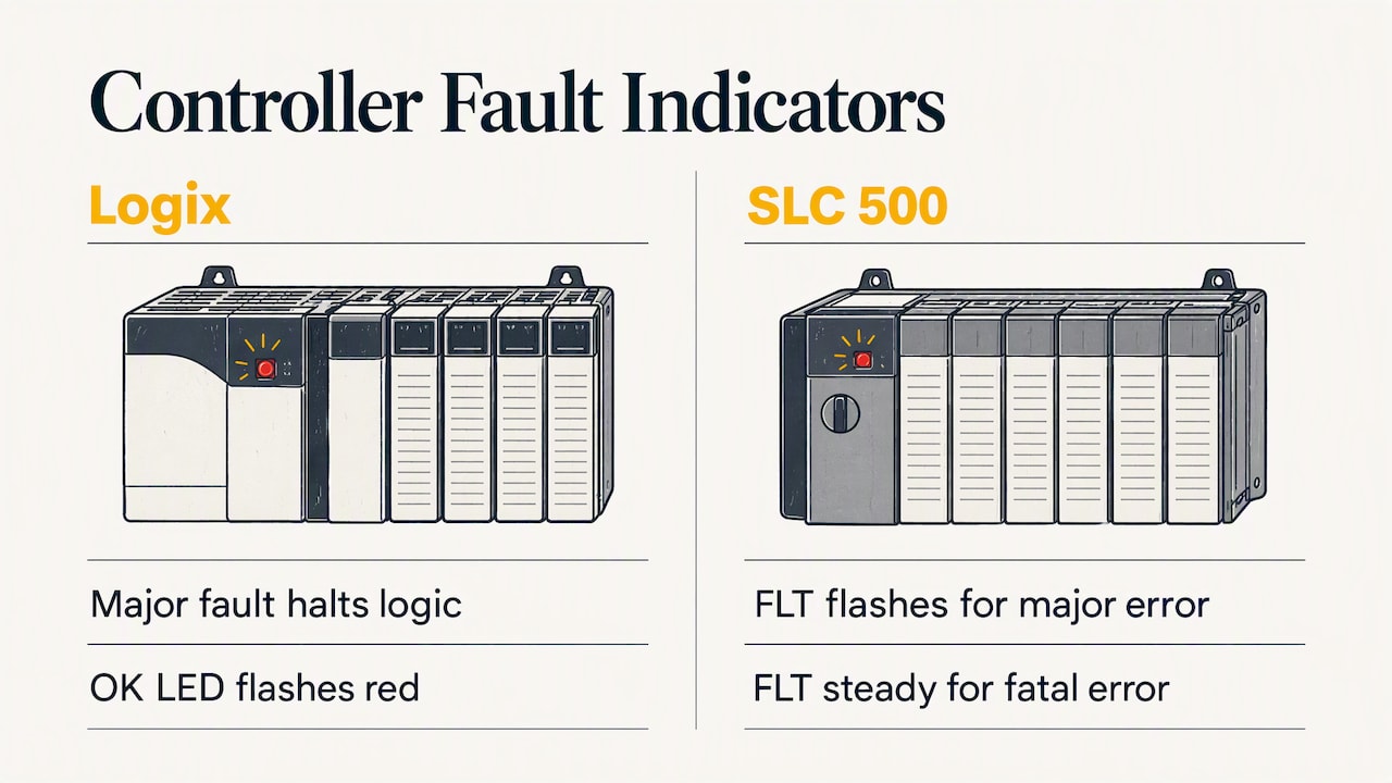
The processor tells you a lot without any software. On Logix controllers, Rockwell’s Major, Minor, and I/O Faults guide states that a major fault halts logic execution and places the controller in faulted mode, and that the OK LED flashes red. If you see that, the program is not running, outputs have gone to their fault state, and you need the fault type and code before anything else.
On older SLC 500 processors, the indicators work differently. Rockwell’s SLC 500 quick-start guide describes the FLT LED as flashing when a major error is detected and steady on for a fatal error. The same guide recommends recording error codes, LED states, hardware series, firmware level and software release before you seek technical assistance. Do that even if you plan to solve it yourself. If you end up calling support, you will have what they ask for in the first minute.
For PLC-5 systems, the PLC-5 quick reference covers status indicators, processor and I/O status, communications and fault codes in one place. For SLC 500 fixed hardware, the installation and operation manual is the troubleshooting reference and documents operating modes, status and processor management. For modular SLC 5/03, 5/04 and 5/05 processors, the installation instructions point you to the SLC 500 Modular Hardware Style User Manual and the Instruction Set Reference for fault-code explanations.
Use the official fault lookup
Do not rely on a forum post for a code’s meaning. Rockwell’s Technical Documentation Center hosts the product manuals, installation instructions and specifications, along with Condition, Event and Fault Code Lookup tools. Search by catalog number or the code itself, and use the manual that matches your exact hardware and firmware revision.
Check the physical layer before the logic
It is tempting to go straight to the ladder rungs, but the layered advice in that US plant support overview is to check control power, fusing, grounding, module seating, backplane connections, link lights, ports, IP settings and recent switch changes before concentrating on project logic. We agree, and it matches what we see in the field. A short checklist:
- Power: Measure the supply at the power supply terminals, not at the breaker. Check fuses and any control transformer.
- Seating: Confirm modules are fully seated in the chassis and that removable terminal blocks are locked in.
- Grounding: Look for loose ground straps and damaged shields, especially on analog and communications wiring.
- Links: Look at the link and activity lights on every port in the path from your laptop to the controller.
- Changes: Ask who touched the panel last, and compare against the drawings.
This stage costs minutes and eliminates a large share of calls. It also protects you from the worst outcome in troubleshooting: editing a working program to fix a loose wire.
When inputs or outputs are not responding
The most common complaint is a device that does not respond. Start by deciding whether the problem is the field device, the wiring, the module or the program. A simple method:
- Check the module indicators. Many I/O modules have status lights for each point. If the light for the input follows the sensor but the tag in the program does not, suspect configuration or the module connection.
- Check the tag online. Open the program online and watch the address or tag. Compare it to the field device’s real state.
- Measure. Use a multimeter at the terminal to confirm voltage is present when the device should be on.
- Check for forces. A forced input or output can make the program look broken when it is doing what it was told. Review forces before you change logic.
- Check the module’s connection and health in the project, not just the lights.
For CompactLogix systems, Rockwell’s installation instructions give a direct answer to a nonresponding module: verify the I/O modules in the project are installed in the same order as in the project, update devices to the latest major and minor firmware revisions, and use RSLogix 5000 online help to identify the nonresponding module. The order point catches many people after a module swap or an added module in the middle of a rack.
A practical example: a photoeye input reads off in the program, but the module light shows it on. The wiring and sensor are fine, so the problem is between the module and the tag. Check the module’s connection status, then the tag’s mapping. The reverse case, a dead light with the sensor powered, sends you to wiring and the sensor itself.

When communications fail or you cannot go online
If the laptop cannot go online, or the HMI shows stale data, treat it as a network problem first. Work from the closest link outward:
- Does your laptop have an IP address in the same subnet as the controller or module?
- Do the link lights on the laptop port, the switch port and the controller port show a connection?
- Can you reach the module another way, for example through its diagnostic web page or over a serial or USB connection?
- Has anything changed on the switch, such as a replaced unit, a changed port or a new device with a duplicate IP address?
- In your software, does the path in the communications dialog match the actual route to the processor?
Rockwell’s EtherNet/IP troubleshooting application technique notes that diagnosing many communication-module problems requires access to the module’s diagnostic web pages, and that available fields vary by module catalog number, Studio 5000 version and firmware revision. So if a page looks different from a screenshot you found, that is normal. Check the version-matched documentation.
HMI communication loss is a special case worth separating. If the PLC runs fine and the HMI shows bad quality data, check the HMI’s communication path and topic or shortcut before you touch the controller. If you want to build stronger skills on the operator-interface side, our page on Allen-Bradley HMI programming with FactoryTalk View SE shows how those connections are structured.
Common faults: watchdog, lost modules and Program mode
Some faults show up again and again. Knowing why they happen is the fastest way to fix them.
Watchdog timeout
A watchdog fault means a task took longer to finish than its allowed time. The cause is often in the logic, not the hardware. Rockwell documents that excessive repetitions in a FOR instruction can cause the controller watchdog to time out and generate a major fault. If a fault appeared after a program change, look first at loops, large array operations and anything that scans data of variable size. The fault log in the software tells you which task faulted.
Lost module connection
Rockwell explains in its controller information and status manual that module connection loss can be configured to generate a controller major fault, interrupting logic and invoking the Controller Fault Handler. Otherwise, you are expected to monitor module health in your logic. This matters for troubleshooting in two ways. First, a controller that faults when an I/O module drops out is working as configured, so go and find the module. Second, a controller that keeps running with a dead module may hide the problem unless the program watches the module’s status.
Controller in Program mode
A controller sitting in Program mode is not necessarily faulted. Someone may have changed the mode during maintenance, or a key switch may be in the wrong position. Check the mode indicator and the key switch, confirm with operations that the machine is ready, then follow your site’s procedure to return to Run. Do not change modes on a live machine without that confirmation.
Unrecognized or mismatched modules
When the software shows a module as mismatched or the light is flashing, compare the physical catalog number, slot and firmware revision against the project configuration. The CompactLogix guidance above, matching order and firmware, applies here too.
Reset a fault safely
Clearing a fault is the last step, not the first. First, understand the cause. Second, make sure the machine is safe to restart. Third, clear it in the way the manufacturer documents for your hardware.
There is one more caution for those who write fault routines. Rockwell warns in the major, minor and I/O faults guide that a fault routine should be selective and must not be used to continually clear all controller faults. If the routine cannot clear the fault, the Controller Fault Handler is invoked. The lesson for troubleshooting: a program that automatically clears everything can hide a real problem until it is bigger. Clear only the faults you understand and have designed a response for.
A safe reset sequence:
- Secure the machine and follow lockout/tagout where people could be exposed.
- Record the fault type, code and time from the software and the indicators.
- Fix the cause: the wiring, the module, the network or the logic.
- Clear the fault using the documented method for your controller family.
- Return to Run with operations aware, and watch the first cycle.
On legacy SLC 500 processors, keep the processor manuals linked above at hand, because the fault code explanations live there.
Verify the fix
A machine that runs again is not proof that the problem is solved. Confirm it with the controller itself. Rockwell’s controller status guidance says a solid-green I/O status indicator means all module objects are running, and module fault codes identify module faults. Check that indicator, read the module fault codes in the software and confirm there are no new entries in the fault log.
Then run the machine through a normal cycle, including the step where the fault occurred. For an intermittent problem, keep watching it for a full shift if you can. Finally, write down what you found and what you did. A single paragraph in the maintenance log saves the next technician an hour.
A quick symptom-to-first-check table
| Symptom | First check | Where to confirm |
|---|---|---|
| OK LED flashing red | Fault type and code in the software | Major, Minor, and I/O Faults guide |
| FLT LED on an SLC 500 | Flashing means a major error, steady means fatal | SLC 500 quick-start guide |
| I/O point not responding | Module lights, forces, module connection | CompactLogix installation instructions |
| Cannot go online | Subnet, link lights, communications path | EtherNet/IP troubleshooting technique |
| Watchdog fault after a change | Loops and large scans in the faulted task | Instruction set documentation |
| Machine runs but a module is dead | Is module health monitored in logic? | Controller information and status manual |
Build the habit, not just the fix
Good troubleshooters are not people who memorized every code. They follow the same sequence every time. If you are new to the platform, our Allen-Bradley PLC controls for beginners page is a good place to learn how the hardware and software fit together. Understanding the four PLC programming languages used by Rockwell Automation helps when you open an unfamiliar program and need to read it quickly, and a worked Allen-Bradley ladder logic example shows what a healthy rung looks like online.
Perspective
Our view is that troubleshooting is a skill you practice, not a list you memorize. Plants lose time when a technician meets a fault for the first time at two in the morning with a machine down.
That is why we teach with real-life examples and hands-on strategies in the software people actually use on the floor: RSLogix 500, RSLogix 5000, Studio 5000 and FactoryTalk View Studio. We build content for every skill level, so a student can learn what a major fault is and an experienced maintenance technician can sharpen how they isolate one.
We designed our training to be practical and cost-effective, because good fault-finding should not depend on whether a company can afford an expensive classroom course. Try the sequence in this article on a practice project before you need it on a live machine.
the author
Get help with your own fault
If you are stuck on a specific problem, or you want to practice before the next one, we can help. A 90-minute PLC coaching session is $97 per session, and our online PLC coaching starts from $67 per session. For structured learning, see our Allen Bradley PLC training courses, or the yearly PLC training membership at $192 per year.

Bring your controller model, software version and the fault you are seeing, and we will work through it with you.
FAQ
How do I reset an Allen-Bradley fault?
Find and fix the cause first, make sure the machine is safe to restart, then clear the fault using the method documented for your controller family. Rockwell cautions that fault routines should be selective and not used to keep clearing every controller fault, so do not automate a blind reset.
What does a flashing red OK light mean on a Logix controller?
According to Rockwell’s fault guide, a major fault halts logic execution and places the controller in faulted mode, with the OK LED flashing red. Open the software, read the fault type and code, and look it up in the official documentation for your hardware.
Why can’t I go online with my Allen-Bradley PLC?
Start with the basics: IP address and subnet, link lights, the communications path and any recent switch change. If those check out, use the module’s diagnostic web pages, keeping in mind the fields differ by catalog number, software version and firmware.
What are the first steps in any PLC troubleshooting job?
Establish safe conditions, define the exact symptom and ask what changed. Then check power, grounding, seating and connections before you look at project logic. That order saves the most time.
Sources
- Technical Documentation Center, Rockwell Automation
- 1785 PLC-5 Programmable Controllers Quick Reference
- Major, Minor, and I/O Faults
- Logix 5000 Controllers Information and Status
- Ethernet SLC 500 Processors Quick Start
- SLC 500 Fixed Hardware Style Installation and Operation Manual
- SLC 5/03, 5/04 and 5/05 Modular Installation Instructions
- CompactLogix Controllers Installation Instructions
- Troubleshoot EtherNet/IP Networks Application Technique
- FOR instruction, Studio 5000 Logix Designer
- Rockwell Automation Support: How US Plants Can Fix Issues