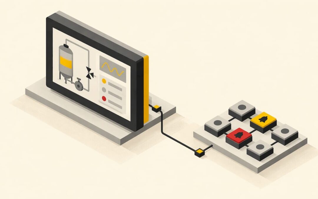
The fastest way to learn HMI work is to study complete, small screens and ask what operator task each one supports. This article walks through six practical examples (a pumping station, a conveyor, a Hand/Off/Auto selector, an alarm screen, a tank level display and a scaled analog value), shows how each connects to PLC tags, and finishes with a troubleshooting routine for when the screen and the controller disagree.
TL;DR
- A good HMI screen answers one operator question: what is running, what is wrong, what do I do next. Design from the task, not from the available graphics.
- Every on-screen value is a PLC tag with a readable name, a scaling rule and, where needed, an alarm. Plan the tags before you draw anything.
- Keep backgrounds subdued, reserve intense color for alarms, and never use color as the only signal of state.
- When a screen shows nothing or the wrong value, check communication settings and addressing first, then the tag itself.
- Practice on real software with a reviewed project. Our FactoryTalk HMI training is built around that approach.
Table of Contents
- What “practical” means for an HMI example
- Example 1: A pumping station overview
- Example 2: A conveyor with animated status
- Example 3: A Hand/Off/Auto selector
- Example 4: An alarm screen operators can act on
- Example 5: A tank level screen with restraint
- Example 6: Turning raw PLC data into a readable value
- Plan the tag database before the screens
- How to organize screens by operator task
- Testing and troubleshooting an HMI
- Our perspective: learn on complete projects
- Where to go from here
- Practice with an instructor
- FAQ
- Sources
What “practical” means for an HMI example
An HMI (human-machine interface) is the screen an operator uses to see what a machine or process is doing and to give it commands. The PLC (programmable logic controller) runs the control logic; the HMI reads and writes the PLC’s tags, which are named memory locations such as a motor run status or a tank level.
Most searches for HMI examples are really three requests in one. Some people want to see finished screens (design). Some want to know how a button or a number gets wired to a tag (programming). Some want to know why their screen shows dashes instead of data (troubleshooting). The examples below cover all three, because on a real job you do them in the same afternoon.
A useful example has four parts: the operator task, the tags behind it, the screen objects that show or change those tags, and the failure you should expect. We use that structure throughout.
Example 1: A pumping station overview
A pumping station is a good first screen because its tasks are simple. The operator wants to know which pumps are running, whether anything has faulted, and how long each machine has been operating.
Rockwell Automation publishes a Solids Pumping Station example that pairs a Studio 5000 controller program with FactoryTalk Optix screens to monitor equipment status and operating time, including remotely. It is a useful model of how a controller project and a screen project are built together rather than one after the other.
Tags behind it: for each pump, a run status bit, a fault bit, a hand/auto mode bit and an elapsed run-time value.
Screen objects: a status lamp per pump, a numeric display for hours, and a navigation button to a detail screen.
Where it goes wrong: run-time totals that reset because the counter lives in a program routine that gets reinitialized. Keep totalizers in retained memory and document where they live.
Example 2: A conveyor with animated status
Conveyors show why the placement of motion matters. One widely cited tip is that animating a box’s position on a conveyor gives a quick, efficient indication of conveyor status, as described in this list of HMI tips. We do not link a page we did not use, so treat the principle as the lesson: animation earns its place only when it tells the operator something that a static icon cannot.
For a conveyor, that means:
- Motor status shown by a symbol that changes shape or fill, not only color.
- A product-present indication fed by a photo-eye tag.
- A single jam or overload message placed next to the conveyor, not on a separate page.
The guidance in Rockwell’s Process HMI Style Guide is to avoid gratuitous animation. A spinning gear on every motor is decoration. A moving box that stops when the belt stops is information.
Example 3: A Hand/Off/Auto selector
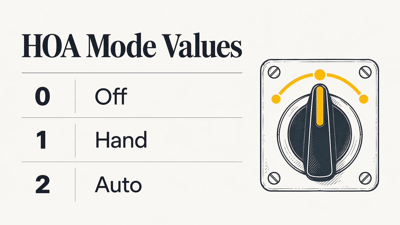
Maintenance technicians use this screen more than anyone. A Hand/Off/Auto (HOA) switch lets the operator run a device manually, stop it, or leave it under automatic control.
Maple Systems’ sample project catalog includes a Hand/Off/Auto screen built as a three-position switch from set-word or set-bit/set-word objects. The idea carries to any platform: one control, three positions, one tag.
Tags behind it: a single integer mode tag (0 = Off, 1 = Hand, 2 = Auto) is easier to maintain than three separate bits, because it cannot be in two states at once.
Screen objects: a three-position selector that writes the integer, plus a lamp that reads back the actual state from the PLC.
Where it goes wrong: showing the position the operator pressed rather than the value the PLC confirms. Always display the feedback tag. If the PLC rejects a request, such as Hand mode while an interlock is active, the screen must show the truth.
If you work in FactoryTalk, our note on button behavior in FactoryTalk covers a common failure with momentary buttons that stay latched.
Example 4: An alarm screen operators can act on
Alarm screens fail when everything is an alarm. Rockwell’s FactoryTalk View Machine Edition guide stresses that alarm planning should specify the conditions that trigger each alarm and how operators are notified. Write that down before you configure anything.
A working alarm design has these pieces:
- An alarm banner visible on every screen, showing the most recent or highest-priority alarm.
- An alarm list with time, tag description, priority and acknowledgment status.
- A history view that lets someone filter by date range after the shift is over.
Maple Systems’ Alarms and Events sample demonstrates exactly that set: an Alarm Bar, an Alarm Display, an Event Display and date-range selection in history mode.
The style guide advises encoding alarm priority with more than color, for example adding a number, shape or position, so the display still works for color-blind operators and on a washed-out panel. Each alarm should also tell the operator what to do, or point to where that is written.
Example 5: A tank level screen with restraint
The temptation with a tank is a bright blue animated fill. The better approach is simple: a gray bar, the numeric value with units, the setpoints marked, and a short trend beside it. A high-performance HMI overview from ISA treats this restraint as a performance aid: subdued graphics reduce distraction, and trends plus carefully encoded alarms make important deviations easier to notice.
The same Rockwell style guide recommends showing important trends near the values they explain. A level of 62% means little. A level of 62% that has fallen steadily for twenty minutes tells the operator the outflow is greater than the inflow.
In practice:
- Use subdued backgrounds and neutral equipment colors.
- Reserve red and yellow for alarm states so they stand out when they appear.
- Show units next to every number.
- Place the trend next to the value, not on a separate page.
For a deeper layout discussion, see our guide to HMI screen design: layout, color and alarm practices.
Example 6: Turning raw PLC data into a readable value
This is the programming example most engineers need first. A pressure transmitter outputs 4 to 20 mA. The analog input card converts that to an integer count. The operator needs to see psi.
Suppose the scaled range is 0 to 100 psi and the card reports 0 to 16,383 counts across the span (your card’s range will differ, so check its documentation). The scaling is linear:
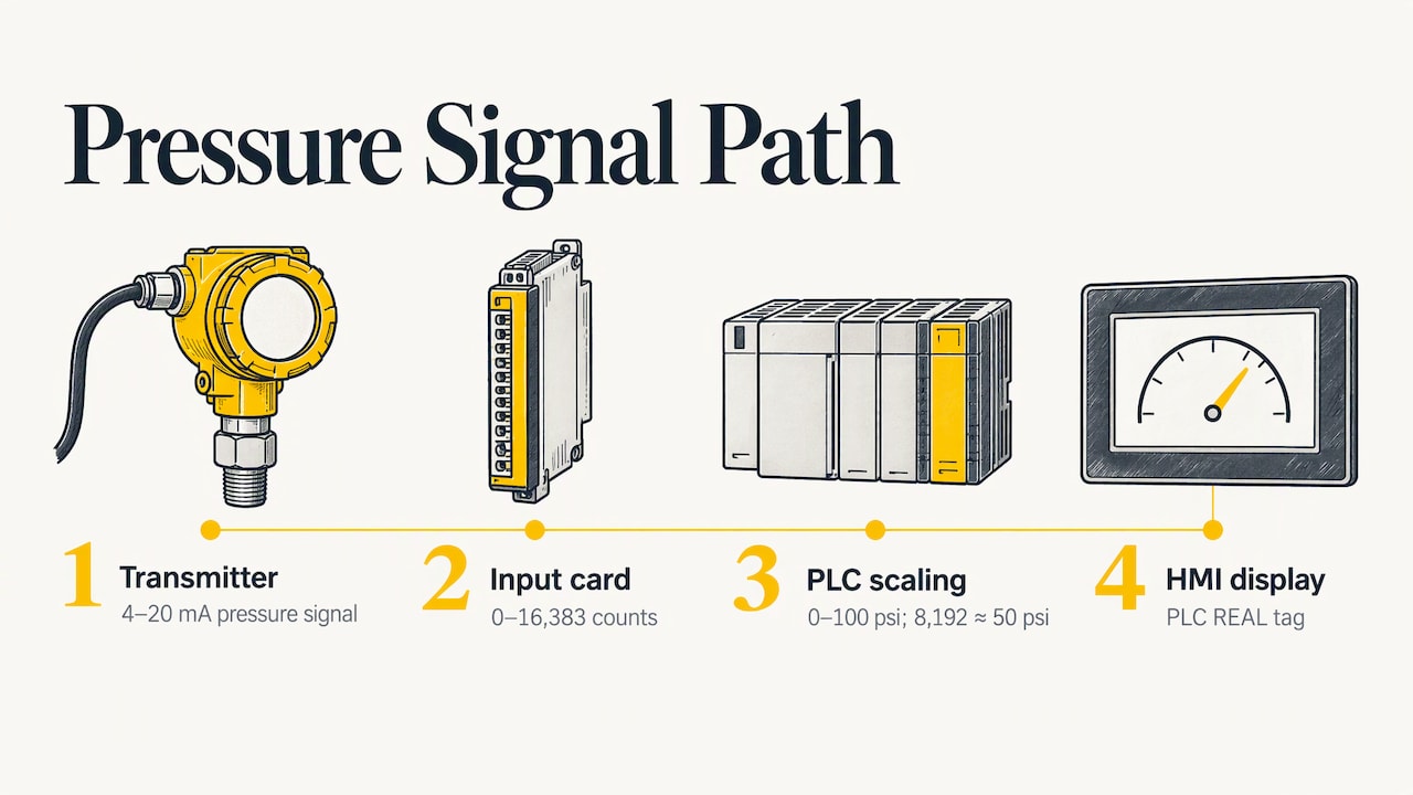
psi = raw / 16383 * 100
A reading of 8,192 counts is about 50 psi. Where you do this math matters. Scale in the PLC, store the result in a REAL tag, and let the HMI display that tag. If you scale in each screen object instead, you will eventually have two screens showing two different values for one transmitter.
The same idea applies to strings and comparisons. Maple Systems’ Macro Basics sample compares two values, writes strings to ASCII displays and sums registers by reading them into an array, which shows how much of this work is just reading, converting and writing tags in a consistent way.
Plan the tag database before the screens
Rockwell’s FactoryTalk View ME guide recommends building the tag plan from process documentation, controller addresses, machinery documentation and alarm requirements. In other words, the screen is the last thing you design.
The same guide ties maintainability to clear naming and organized tag groups. That is the payoff for the person who troubleshoots at 2 a.m.: a tag named Pump1_Run_Sts tells them where to look, while N7:14 does not.
A simple naming pattern that works on most projects:
| Part | Example | Purpose |
|---|---|---|
| Equipment | Pump1 |
Which machine |
| Function | Run |
What it does |
| Type | Cmd, Sts, Alm, SP |
Command, status, alarm or setpoint |
Write the plan once, share it with whoever programs the PLC, and keep the HMI and controller names identical so a cross-reference search finds both.
To see how the two sides talk to each other in Rockwell software, read how an HMI communicates with a PLC program in FactoryTalk.
How to organize screens by operator task
Rockwell’s style guide describes a display hierarchy: Level 2 process-unit displays are the primary operating screens for routine monitoring and control, Level 3 supports detailed diagnosis, and Level 4 provides support such as diagnostics and help. Navigation should be consistent across all of them.
An HMI design paper from Opto 22 adds a practical order of work: build the Level 2 task screens first, then design the Level 1 overview around the subsystems. It recommends that the overview show KPIs, high-priority alarms with acknowledgment status, major equipment status, key trends and the severity of abnormal conditions.
For a small machine with one screen, you can fold these levels together. The test is the same: can an operator find the right control in two touches, and can they tell at a glance whether the machine is normal?
Testing and troubleshooting an HMI
Most HMI faults are not screen faults. They are communication, addressing or tag problems. Work in this order.
- Check the connection. Confirm the communication parameters, the PLC address and the network configuration. Maple Systems’ PLC No Response sample covers these three and includes objects that change connection parameters at runtime, which helps when a panel is moved to a different network.
- Check the tag reference. In FactoryTalk View ME you can use direct-reference controller tags or HMI tags. A typo in either gives a missing value. Use the cross-reference and diagnostics tools to find tags that are missing or wrong.
- Check the data type and scaling. A value off by a factor of ten is usually a scaling or data-type mismatch, not a wiring fault.
- Check permissions and interlocks. If a button does nothing, the PLC logic may be rejecting the command. Read the controller, not just the screen.
- Simulate before installing. In a pharmaceutical project described by Inductive Automation, engineers built a simulated environment with a PLC simulator to run software acceptance testing before installation. Even a small shop gains from testing every screen against simulated values, including the alarm limits.
For a structured look at these failures, see our page on troubleshooting HMI problems.
Our perspective: learn on complete projects
Reading about HMI design rules is easy. Applying them to a real tag list, a real alarm philosophy and a real controller is where people get stuck. That is why we teach with real-life examples and hands-on strategies, using the industry-standard software engineers meet on the job: RSLogix 500, RSLogix 5000, Studio 5000 and FactoryTalk View Studio.
The examples in this article share one habit: start from the operator’s task, then work back to the tags. In our training we keep that order, and we keep the content up to date so the screens you build match current practice. The material is structured for all skill levels, so a student building a first status lamp and a maintenance technician chasing a communication fault can both find a starting point.
If you want a person to look at your own project, our coaching sessions put an instructor on your screens and your tags rather than on a generic demo.
the author
Where to go from here
If you want a structured path rather than a collection of samples, our HMI training course guide explains what to learn and in which order. For Rockwell users, the FactoryTalk View training project teaches the same ideas through a game, which is a low-stakes way to practice buttons, tags and screen navigation.
On the controller side, a screen is only as good as the logic it reads. Our overview of PLC programming controls shows the other half of each example above.
Practice with an instructor
Our Allen Bradley PLC and FactoryTalk View ME courses cover the controller and screen sides together, and you can see the full list on our PLC training page. If you would rather work on your own screens, a 90-minute PLC coaching session is $97 per session, and our online PLC coaching starts from $67 per session. The Yearly PLC Training Membership is $192 per year.

Teams that want several people to build the same skills can start from the online PLC coaching page and tell us which software and machines they use.
FAQ
What is a good first HMI project for a beginner?
Build a single-motor screen: a start button, a stop button, a run lamp, a fault lamp and a run-time display. It uses commands, status, an alarm and a counter, which are the four building blocks of larger screens. Wire each object to a clearly named tag.
What is the difference between HMI design and HMI programming?
Design decides what the operator sees and in what order: layout, color, navigation and alarm presentation. Programming connects those objects to PLC tags, scales values, writes commands and configures alarms. Good projects plan both together, starting from the tag list.
Why does my HMI show the wrong value or no value?
Start with the communication settings and PLC address, then verify the tag name or reference exists in the controller. If the number is wrong rather than missing, check data type and scaling. Cross-reference tools in your HMI software help locate missing or incorrect tags.
Should I use bright colors and animation to make a screen clear?
No. Rockwell’s style guide advises subdued backgrounds, intense color only for alarms, no reliance on color alone for state, and no gratuitous animation. Use motion only when it shows something that matters, such as product moving on a conveyor.
Which software should I practice HMI programming on?
Use the platform you will meet at work. For Allen-Bradley environments that is usually FactoryTalk View ME or SE alongside Studio 5000 or RSLogix. Our courses cover these tools, and the FactoryTalk ME training is listed on our training page.
Sources
- Solids Pumping Station, Rockwell Automation
- Sample Projects, Maple Systems
- Process HMI Style Guide, Rockwell Automation
- FactoryTalk View Machine Edition User’s Guide, Rockwell Automation
- Building an HMI that Works, Opto 22
- High Performance HMI Overview, ISA
- Meeting 21 CFR 11 Standards for Pharma, Inductive Automation