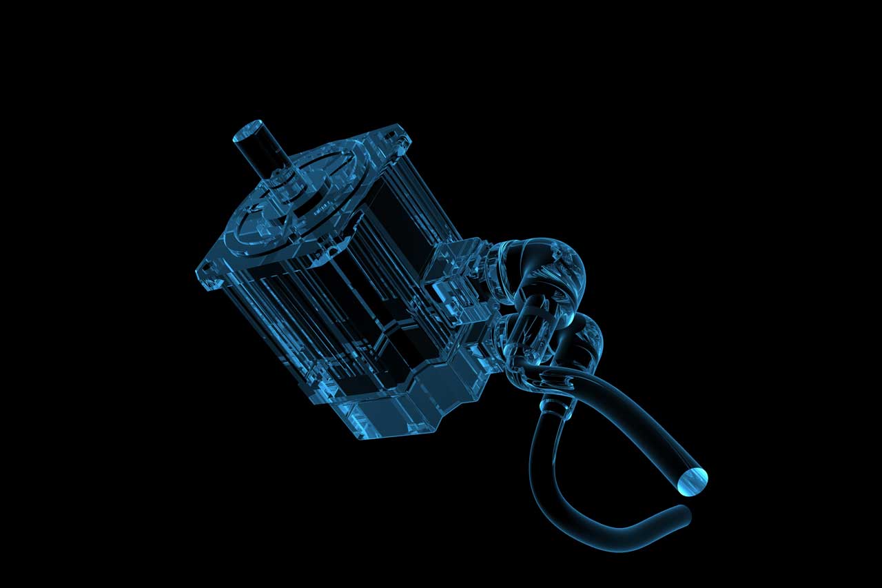
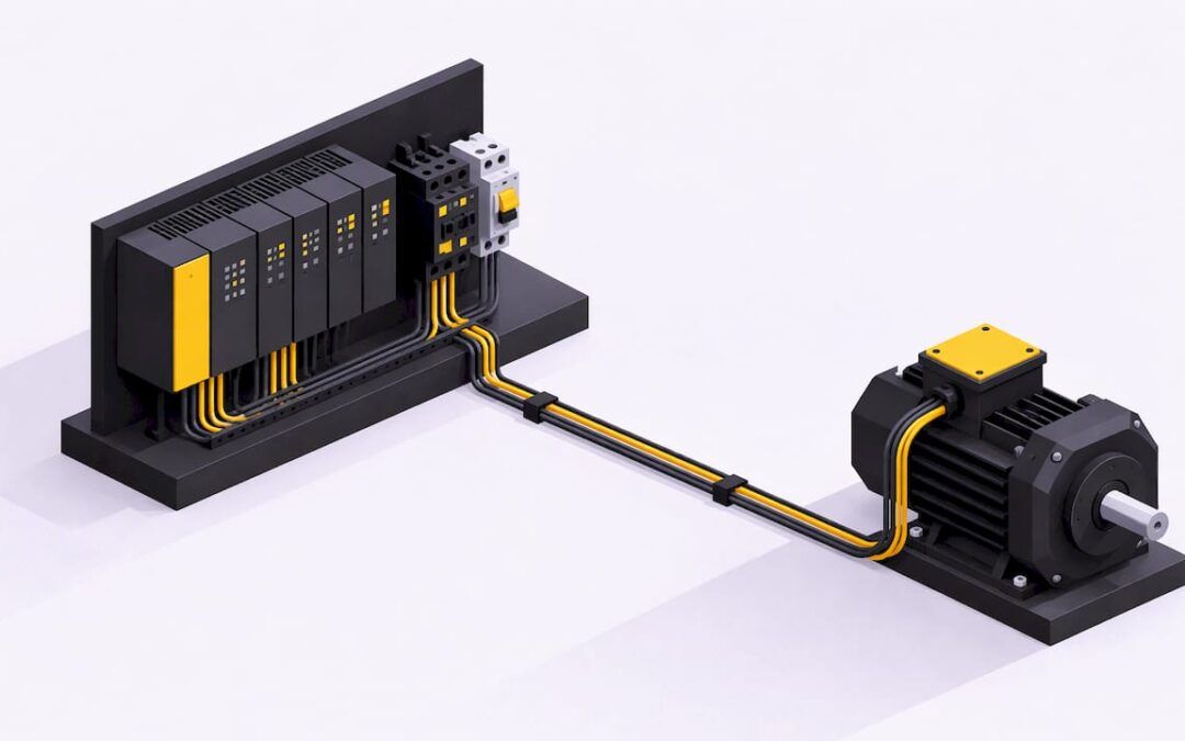
A PLC does not drive a motor directly. It reads inputs such as a start button, a stop button and an overload contact, runs your program, and switches an output that energizes a relay, a contactor coil or a drive command. The contactor or drive then connects the power to the motor. Get that chain right (input, logic, output, power device, motor) and every motor-control job, from a simple conveyor to a reversing pump, follows the same pattern.
This guide walks through that chain for working engineers, maintenance techs and students. You will see how a start-stop rung works, how to wire the PLC to a starter, how interlocks and overloads fit in, when to add a VFD, and how to troubleshoot a motor that will not run.
TL;DR
- A PLC sends a low-power output signal to an intermediate device (relay, contactor or VFD), which switches the motor power.
- The classic start-stop circuit uses a seal-in contact, a stop input and an overload input. Wire the stop button normally closed so a broken wire stops the machine.
- Interlocks, overload protection and E-stops belong in the design from the first rung, and U.S. installations follow NEC Article 430.
- Use a VFD when you need speed control. For reversing, interlock forward and reverse so both can never be on together.
- Troubleshoot from the control circuit toward the motor: if the contactor does not pull in, start with the control side.
Table of Contents
- What a PLC actually does in motor control
- The signal chain from PLC to motor
- The start-stop circuit, rung by rung
- Overloads, disconnects and emergency stops
- Reversing and variable speed: adding a VFD
- Troubleshooting a motor that will not run
- Our perspective on learning motor control
- Practice with structure and support
- FAQ
- Sources
What a PLC actually does in motor control
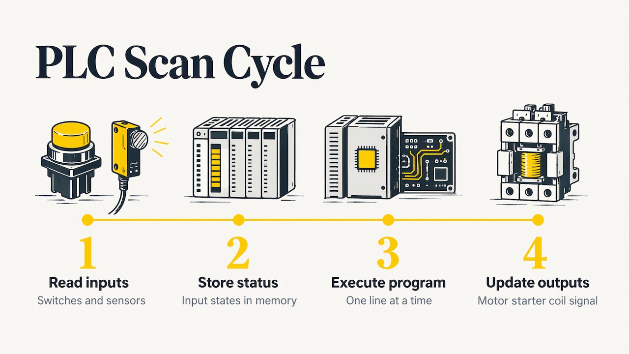
A PLC is a microprocessor-based system that accepts input data from switches and sensors, processes it according to a stored program, and generates output signals to devices to perform a function, as IAEI Magazine describes it. Each scan, the PLC reads the status of every input, stores it in memory, executes the program one line at a time, and then updates the outputs, for example the coil of a magnetic motor starter. The time that cycle takes is the scan time.
The key point for motor work: the PLC provides an output signal to an intermediate device such as a relay or a variable frequency drive, and that device commands the motor on. The PLC’s output card is rated for small currents. The industry-typical figure for a digital output is 0.5 to 2 A, nowhere near what a motor draws.
Why use a PLC at all instead of hardwired relays? Because rules become easy to change. A start command can be accepted only if guard sensors show the guards are in place and no fault is active, a rule Farnell gives as a typical example. The same logic can monitor speed, current and fault status, and that is what makes predictive maintenance possible.
Ladder logic is still the standard language for this work. It is modeled on the flow of work through a scheme of electrical relays, which is why electricians and engineers pick it up quickly. If you are new to reading it, our guide to reading PLC ladder logic is a good first stop.
The signal chain from PLC to motor
Think of five links:
- Field inputs: start pushbutton, stop pushbutton, overload contact, limit switches, guard sensors.
- PLC program: the ladder logic that decides when the motor may run.
- PLC output: a digital output module, typically 24 VDC.
- Power device: an interposing relay, a contactor or starter, or a VFD.
- Motor: fed through the contactor’s main contacts.
A commonly described architecture runs from the PLC digital output (24 VDC) to a relay coil, then a normally open relay contact to the contactor coil, then the contactor’s main contacts (L1/T1, L2/T2, L3/T3) to the motor terminals U, V and W. Per the same source, the contactor should be rated at or above the motor’s FLA times 1.25.
When the contactor coil suits the PLC output, you can connect the output directly to coil terminal A1, with A2 going to the 0 VDC rail or through the overload relay. If the coil voltage or current is higher than the output can handle, add an interposing relay.
Sizing and starting current
Motors draw several times their running current at startup. That affects contactor selection, wire sizing and protection settings. For a deeper look at the numbers, see this explainer on motor inrush current and how to limit it.
The start-stop circuit, rung by rung
This is the first circuit every controls person learns, and it is worth building until it feels automatic. The example below follows a widely used three-phase motor program:
| Address | Device | Field contact type |
|---|---|---|
| I0.0 | Start pushbutton | Normally open |
| I0.1 | Stop pushbutton | Normally closed |
| I0.2 | Overload relay contact | Normally closed |
| Q0.0 | Motor starter coil | Output |
The rung has the start contact in parallel with a normally open Q0.0 contact (the sealing contact), then the stop and overload contacts in series, ending at the Q0.0 coil. Press Start and the output energizes. Q0.0’s own contact now holds the rung true, so the motor keeps running after you let go. Break the series path and Q0.0 de-energizes, which opens the sealing contact and turns the motor off.
Why the stop button is wired normally closed
This trips up beginners. In the field, the stop button is wired normally closed so that a broken wire stops the machine. The PLC input therefore reads 1 when nobody is pressing it, and the program uses an examine-if-closed instruction (XIC in Rockwell, a normally open contact in Siemens LAD) so the rung conducts while the input is 1, as one controls writer explains. The same logic applies to the overload contact: if its wiring fails, the motor must stop.
On the hardwired side, the seal-in works the same way. The contactor feeds itself through its own auxiliary contact (terminals 13-14) and drops out when stop is pressed, the overload trips or the supply fails.
Add the permissives
A real motor rung does more than start and stop. If any interlock input is active, the program should treat it as a fault and prevent the motor from starting. It must also stop the motor when stop is pressed or when an interlock signals a fault or safety issue. Typical inputs include:
- Motor vibration high
- Overload tripped
- Motor temperature high
- Guard barrier sensors
- A local/remote selector showing whether the panel or the PLC is in control
Those are the inputs Farnell lists for a typical motor application. Practice building this rung with our Allen Bradley ladder logic example, or work through a full sequence in the box sorting conveyor lesson in Studio 5000.
Overloads, disconnects and emergency stops
Safety hardware is not a software feature. The PLC can monitor and respond, but the protective devices have to be right on their own.
NEC requirements (United States). The code treats the controller as a device that must be able to start and stop the motor and interrupt locked-rotor current (Section 430.82(A)). Overload devices must trip at no more than 115% of nameplate FLA for motors with a 1.15 or higher service factor, and 125% for others (Article 430.32). Branch circuit conductors are sized at not less than 125% of full-load current, using the NEC tables rather than the nameplate. A disconnect must be within line of sight of the controller (430.102). Always confirm values against the current adopted code and your local authority having jurisdiction before you design or modify anything.
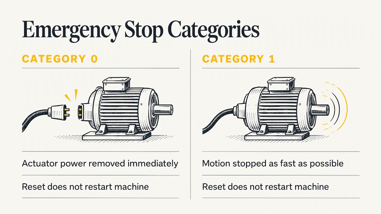
Emergency stops. IEC 60204-1 says the emergency stop function must override all other functions in all modes. Power to actuators is removed immediately (stop category 0) or the hazardous motion is brought to a stop as fast as possible (stop category 1), and resetting must not restart the machine. In practice: do not route an E-stop only through a PLC input. Wire it into the safety circuit so it works even if the program hangs, and require a deliberate start command after reset.
If you are designing safety functions, have a qualified controls or safety engineer review the design. Risk assessment for guarding and E-stop categories is not something to improvise from a tutorial.
Reversing and variable speed: adding a VFD
Reversing starters
For reversing with contactors, the two contactors must be interlocked so no short circuit can occur when switching. The standard practice is to use both software interlocks (the forward output rung includes a normally closed reverse output contact, and vice versa) and a hardware mechanical or auxiliary-contact interlock. Never rely on software alone for this.
When a drive makes sense
A VFD controls the speed and torque of an AC induction motor by varying output frequency and voltage. Discrete signals handle states such as start and stop, while analog signals (0-10 VDC or 4-20 mA) set a continuous speed reference. A PLC can also talk to drives over a communications protocol, with Modbus long being the most popular, which allows run commands, direction and real-time acceleration and deceleration changes.
VFDs pay off most on pumps and fans. One industry source cites 20-60% energy savings in those applications by eliminating throttling losses, and notes they are a poor fit for constant-speed loads and very small motors under 1 HP.
As a wiring example, a PowerFlex 4 with an SLC 500 or MicroLogix connects terminal 2 (FWD) and terminal 3 (REV) to PLC digital outputs, ties the commons together, and uses an interlock preventing simultaneous forward and reverse. If your plant runs PowerFlex 525 drives, our PowerFlex 525 course covers drive setup alongside PLC control.
Troubleshooting a motor that will not run
A clear method beats guessing. Always lock out and tag out before touching the circuit, then work in order:
- Does the PLC output turn on? Check the output LED and watch the rung online. If the rung is false, find which contact is blocking it: stop, overload, interlock or permissive.
- Does the contactor pull in? If not, stay on the control side: coil voltage, the overload contact, wiring and the interposing relay. If it pulls in but the motor does not run, look at the power circuit or the motor.
- Walk the power path. Drawing both sides of the circuit helps. The test points are the disconnect, fuses, contactor and overload relay, and the best approach is to start at one end and work toward the motor.
- With a drive, check its own status. A PowerFlex 525 that stops with no fault code is typically caused by an unsatisfied safety status interlock, a wrong control source setting (parameter b012) or a missing stop jumper between terminals 11 and 12.
Maintenance teams that can read the live rung and the schematic together solve these faults in minutes instead of hours. That skill is exactly what practice on real software builds.
Our perspective on learning motor control
Most people learn the start-stop rung from a diagram and then freeze the first time a real motor will not start. The gap is almost never the ladder logic. It is knowing what sits between the output card and the motor, and how to test each piece in order.
We build our training around that gap. Our courses use real-life examples and industry-standard software such as Studio 5000, RSLogix and FactoryTalk View, and we keep the content current so you practice what you will meet on a plant floor. We designed the material for all skill levels, so a student can start with a seal-in rung while an experienced technician can move on to drives and servo motion.
Our advice: build the same motor circuit three times. First as a plain start-stop, then with overload and interlock inputs, then with a VFD and fault feedback. By the third pass you stop memorizing symbols and start designing.
the author
Practice with structure and support
Reading about motor circuits is a start, but the skill sticks when you build them and get feedback. We offer on-demand PLC and HMI courses, including Allen Bradley PLC training and the PowerFlex 525 course, plus optional coaching and membership.

If you want help with a specific motor circuit, a 90-minute PLC coaching session is $97 per session, and online PLC coaching starts from $67 per session. The yearly PLC training membership is $192 per year. Not sure where to begin? Start with our PLC ladder logic basics for beginners, or visit Online PLC Support to see everything we offer.
FAQ
Can a PLC connect directly to a motor?
No. A PLC output is a low-power signal, so it switches an intermediate device such as a relay, contactor or VFD. That device carries the motor current. Some small contactor coils can be driven straight from a PLC output, but the motor itself never connects to the PLC.
Why is the stop button wired normally closed?
A normally closed stop contact fails safe: if the wire breaks or the contact opens, the PLC sees the same condition as a pressed stop and the motor stops. The input reads 1 while the button is untouched, so the program uses an XIC (Rockwell) or normally open contact (Siemens LAD) in the rung.
When should I use a VFD instead of a contactor?
Use a VFD when you need to control speed or torque, ramp acceleration, or save energy on variable loads like pumps and fans. A contactor is simpler for constant-speed, on/off duty. Many plants use both, depending on the machine.
Can I teach myself PLC programming?
Yes, many people do. Start with ladder logic basics, build small motor circuits in simulation software, and then move to real hardware or guided practice. Structured lessons with feedback shorten the learning curve, especially for troubleshooting and drive integration.
Sources
- Introduction to PLCs, IAEI Magazine
- Industrial PLC motor control, Farnell
- Industrial PLC motor control, Newark
- PLC Motor Control Fundamentals, Industrial Monitor Direct
- How to Wire Motor Starters and Contactors, control.com
- PLCs for drives in industry, Nidec Drives
- Basic PLC program for control of a three-phase AC motor
- Seal-in circuit: contactor wiring diagram and PLC ladder
- Selecting Motor Controllers, EE Power
- NEC Article 430 Requirements for Motor Control Centers, MCC Depot
- IEC 60204-1 text (ДСТУ EN 60204-1:2014)
- VFD Control Fundamentals, Industrial Monitor Direct
- PowerFlex 4 forward reverse control with PLC
- When to Use Variable Frequency Drives, AMED US
- Troubleshooting a motor control circuit, Control Design
- Fix PowerFlex 525 Stopped Running, Industrial Monitor Direct