PLC start-stop logic is a ladder rung that lets a momentary Start pushbutton turn a motor on and keeps it running until a Stop pushbutton or a protective device breaks the rung. The trick is the seal-in: the output’s own contact sits in parallel with Start, so the output holds itself on after you let go of the button. This guide shows the rung, the wiring behind it, the one-button variation, the safety limits, and a checklist for when it misbehaves.
TL;DR
- A start-stop circuit is a normally open Start contact, in parallel with the output’s own contact, in series with the Stop condition, driving one coil.
- Wire Stop as normally closed in the field so a broken wire stops the machine. The PLC then reads it as a 1 while the button is at rest, so you program it with an examine-if-closed (normally open) contact.
- A one-button version works differently: it detects the press edge and toggles a state bit instead of sealing in.
- E-stops and overload protection stay hardwired outside the PLC. The program is never your only safety layer.
- Most faults come from wrong addresses, a missing seal-in branch, or a Stop contact of the wrong type.
Table of Contents
- How a PLC start-stop circuit controls a motor
- The seal-in rung, step by step
- Wiring Start and Stop: the NC Stop trap
- I/O addresses on common platforms
- Seal-in versus latch and unlatch
- The one-button start-stop circuit
- Safety: what stays outside the PLC
- Troubleshooting a start-stop rung
- Our perspective
- Get help with your own start-stop circuit
- FAQ
- Sources
How a PLC start-stop circuit controls a motor
A PLC does three basic jobs over and over: it reads inputs, executes the program, and updates outputs. IAEI Magazine describes these as the PLC’s three basic tasks, and the time one pass takes is the scan time. If you want to see how that loop affects your rungs, our guide to the PLC scan cycle covers it in detail.
For a motor, the sequence looks like this:
- The Start pushbutton is a momentary normally open (NO) device. Pressing it turns its input on.
- The Stop pushbutton removes the run condition. Pressing it drops the output.
- The output energizes the coil of a motor starter or contactor, and the contactor’s power contacts feed the motor.
The PLC output does not drive a large motor directly. It energizes a contactor coil, and the contactor switches the motor power. Per the same IAEI overview, the NO Start requests operation, and the Stop takes the run condition away and de-energizes the output when pressed.
If you are still getting comfortable with reading rungs left to right, start with our page on reading PLC ladder logic and come back.
The seal-in rung, step by step
Here is the classic rung. Think of power flowing from the left rail, through contacts, to the coil on the right.
        Start        Stop          Motor_Run
  |-----] [----+----]/[ or ] [----------( )-----|
  |            |   (see wiring)                 |
  |  Motor_Run |                                |
  |-----] [----+                                |
In plain terms: Start is in parallel with a contact that carries the same address as the output coil (Motor_Run). The Stop condition is in series with that whole parallel block, then the coil.
What happens when you press Start
You press Start. Its contact closes, power flows through Stop (which is passing), and the Motor_Run coil turns on. The moment the coil is on, the Motor_Run contact in the parallel branch closes too. Now there are two paths to the coil.
What happens when you release Start
Start opens again, but the Motor_Run contact still provides a path. The coil stays energized. This is what “sealed in” means. As Control.com explains it, the logic branches around the input conditions using the same variable as the output coil, so the start command can disappear while power still flows to the output.
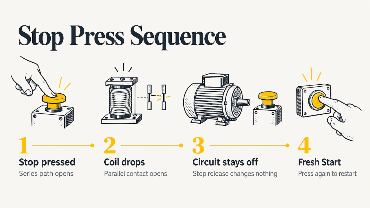
What happens when you press Stop
Stop breaks the series path. The coil drops, the Motor_Run contact in the parallel branch opens, and the circuit is back to its starting state. Releasing Stop does nothing by itself. You need a fresh Start press. The same happens if an overload or other protection condition in the series path opens.
Why a power loss does not restart the motor
Because the seal-in contact opens when the coil drops, a power interruption leaves the circuit unlatched. A start-stop circuit guide notes this gives undervoltage protection: when power returns, the motor stays off until someone presses Start again. This is a useful property for anyone working near the machine.
Wiring Start and Stop: the NC Stop trap
This is where beginners get tripped up. The ladder shows symbols, but the symbol must match the state of the input bit, not the label on the pushbutton.
| Device | Field wiring | State at rest | Ladder contact you use |
|---|---|---|---|
| Start pushbutton | Normally open | Input off (0) | Normally open (examine if closed) |
| Stop pushbutton | Normally closed | Input on (1) | Normally open (examine if closed) |
The Stop pushbutton is wired normally closed so that a broken wire or loose terminal looks the same as a press: the machine stops. Control.com’s ladder diagram textbook explains that the NC button delivers a 1 while unpressed, so the program reads it with a normally open contact. When Stop is pressed, the bit drops to 0 and the rung breaks.
That same text makes a point worth remembering: the “normal” state of a switch is its state at rest, with no stimulation, not necessarily the state during normal operation of the process. That is why a normally open virtual contact for a normally closed pushbutton sits in the closed (passing) state while the machine runs.
A quick sanity check
With the machine idle and nothing pressed, look at the online ladder in your software:
- The Start contact should show open (no power flow).
- The Stop contact should show closed (power flow).
- The coil should be off.
If Stop shows open at rest, either the wiring is NO instead of NC, or the instruction type is inverted. Fix that before anything else.
I/O addresses on common platforms
The logic is identical across brands. Only the addressing and the software change. A relay-to-PLC conversion guide maps typical first input and output addresses like this:
| Platform | First input | First output |
|---|---|---|
| Allen-Bradley MicroLogix | I:0/0 | O:0/0 |
| Siemens S7 | %I0.0 | %Q0.0 |
| Omron | 0.00 | 100.00 |
| Mitsubishi | X0 | Y0 |
In Mitsubishi MELSEC programs, the latching version uses a NO contact S1 for Start and an NC contact S2 for Stop, with output Y000 as an OR branch that keeps power flowing once the momentary switch is released. The same page also shows SET Y000 and RST Y000 instructions as an alternative.
In Studio 5000 or RSLogix, you would typically use tags (such as Start_PB, Stop_PB, Motor_Run) rather than raw addresses. Descriptive tag names make a seal-in rung readable at 2 a.m. during a breakdown. If you want to build one in Studio 5000, our walkthrough on ladder logic basics with a box sorting conveyor puts these pieces into a working project.
Seal-in versus latch and unlatch
You can also hold an output with SET/RESET (latch/unlatch) instructions. Both approaches work, and the choice affects readability and behavior.
Control.com’s Shawn Dietrich points out in his comparison of the two methods that seal-in keeps the start and stop conditions together in one place, which suits starting a fan motor or a robot task. As start and stop conditions multiply, the branches grow and the rung can spill onto a second row. With momentary coils, multiple start or stop sources need extra handshake bits.
A practical rule we use when teaching:
- Use seal-in for a simple motor run command, where the output should drop on any fault or power loss.
- Use latch/unlatch when several different events must set or clear a state and you want each in its own rung. Be deliberate about what the state does after a power cycle or a program mode change.
Stop-dominant logic
What if Start is held down or stuck while Stop is pressed? Because Stop sits in series with the whole rung, a pressed Stop breaks the path regardless of Start. That is the stop-dominant arrangement, and it is the one you want in nearly every motor circuit. Putting Stop inside the parallel branch alongside Start only (so Start can override it) is the mistake to avoid.
The one-button start-stop circuit
Sometimes there is only one momentary pushbutton, often a lighted one: press once to run, press again to stop. This is not a seal-in rung. It is a toggle.
The basic idea, as a DigiKey TechForum write-up of single-button control puts it, is to watch for the rising edge of the button press and toggle a state variable when it happens. In words:
- Rung 1: if the state bit is on and the button has just been pressed (rising edge), clear the state bit.
- Rung 2: if the state bit is off and the button has just been pressed, set the state bit.
- Rung 3: the state bit drives the output.
The edge detection matters. Without it, the PLC would see the button held down across many scans and flip the state bit back and forth every scan. That is why it is called a one-shot: it passes power for exactly one scan after the button goes from off to on.
Where it differs from two-button logic
| Two-button seal-in | One-button toggle | |
|---|---|---|
| Stop wiring | Separate NC pushbutton | Same button as Start |
| Wire-break behavior | Broken Stop wire stops the machine | A broken wire just looks like “no press” and the machine keeps running |
| Holding mechanism | Output’s own contact | State bit toggled on the press edge |
| Best for | Motors, pumps, conveyors needing a hard stop | Light-duty on/off, lighted pushbuttons, HMI-style toggles |
That wire-break row is the reason serious motor circuits keep a dedicated NC Stop. Even with a one-button toggle on the panel, keep an NC stop or E-stop in the chain.
Safety: what stays outside the PLC
A start-stop rung is a control function, not a safety function. Emergency stop, overload protection and interlocks must still work if the PLC fails or loses power.
The MELSEC iQ-F FX5 User’s Manual says safety circuits must be set up outside the PLC so the system stays safe even during power problems or a PLC failure. It lists an emergency stop circuit, a protection circuit, an interlock circuit for opposite movements, and an interlock to prevent damage at positioning limits. That is Mitsubishi’s wording for its own hardware, but the principle is standard practice across brands.
In practice that means:
- Wire the E-stop so it removes power to the contactor coil circuit directly, not just a PLC input.
- Wire the motor overload contact in the control circuit, and optionally also into a PLC input so the HMI can show the cause of a trip.
- For forward and reverse starters, add a PLC interlock and a mechanical or electrical interlock at the contactors.
- If a task needs a rated safety function (guarding, light curtains, safe torque off), use properly rated safety components and follow your site’s safety procedures and applicable standards. Ask a qualified controls or safety engineer to review the design.
Troubleshooting a start-stop rung
Work from the field to the logic. Go in this order and you will find most problems in minutes.
The motor will not start
- Check the Stop input first. With nothing pressed, the NC Stop input should be on. If it is off, the rung can never go true. Look for a loose terminal, an open E-stop, or a wrong instruction type.
- Check the Start input. Press Start and confirm the input bit turns on in the online view.
- Check every other series condition, such as overload, guard or permissive bits.
- Watch the coil. If the coil turns on in the program but the contactor does not pull in, the problem is the output module, the output wiring or the contactor coil, not the logic.
The motor starts but drops out when you release Start
The seal-in is missing or wrong. Confirm the parallel contact uses the exact same tag as the output coil, that it is a normally open contact, and that it is truly in parallel with Start. A very common error is a seal-in contact that references a different tag than the coil, such as an input feedback bit that is not actually on yet.
The motor will not stop
- Is the Stop contact the right type? A normally closed contact on an NC-wired input will block the rung at rest and opposite behavior follows.
- Is Stop in series with the entire parallel block, rather than in series with Start only?
- Is another rung or a forced bit also writing to the same coil? Search the project for duplicate coils on the same tag.
- Is any bit forced? Forces stay in place until removed. Clear them before concluding the logic is wrong.
The motor restarts after a power cycle
A plain seal-in rung does not do this. If yours does, look for a latch instruction, a retained tag, or logic that auto-starts on the first scan. Decide whether that behavior is intended and safe for the machine and the people around it.
Testing before commissioning
Document the relay schematic, assign I/O, build the rung, and test with force or override tools before commissioning, as the relay conversion guide lays out. Test each failure you care about: Stop pressed, Start held while Stop pressed, a wire pulled off the Stop terminal, and a power cycle.
Our perspective
Start-stop logic is the first rung most technicians write and the one they most often get subtly wrong. The wiring and the logic have to agree, and that is a hands-on skill, not a memorized diagram.
In our training we start every student on a real motor-control example: wire the NC Stop, read the bit online, watch the seal-in carry the coil, then break it on purpose. Once you have seen a pulled Stop wire drop the output, you never forget why Stop is wired normally closed.
We teach on industry-standard software such as RSLogix 500, RSLogix 5000, Studio 5000 and FactoryTalk View Studio, with real-life examples and practical troubleshooting methods. Our aim is clear, structured, cost-effective training that works whether you are a student, a maintenance technician or an engineer building a team’s skills.
For more motor-control patterns such as reversing and interlocks, see our motor control ladder logic guide.
the author
Get help with your own start-stop circuit
If you have a rung that will not behave, or you want to build confidence before touching a live panel, we can work through it with you. A 90-minute PLC coaching session is $97 per session, and online PLC coaching starts from $67 per session. For ongoing learning, the Yearly PLC Training Membership is $192 per year.

Prefer structured courses? Our Allen Bradley PLC training covers programming and troubleshooting from fundamentals upward.
FAQ
What is the difference between a seal-in and a latch in PLC logic?
A seal-in uses the output’s own contact in parallel with Start to hold the coil on, and it drops whenever the series path opens. A latch uses SET and RESET instructions, so the output stays on until a separate reset runs. Seal-in keeps start and stop in one rung, while latching splits them.
Why is the Stop button wired normally closed?
A normally closed Stop means a broken wire or loose connection looks like a press, so the machine stops instead of running with no way to stop it. The PLC input is on at rest, so you program it with a normally open contact in the ladder.
Can I build start-stop logic with one pushbutton?
Yes. Detect the rising edge of the button press and toggle a state bit that drives the output. Keep a separate normally closed stop or E-stop in the chain, because a single button cannot tell a broken wire from a button that was not pressed.
Does the motor restart after power returns?
With a standard seal-in rung it does not. The coil drops when power is lost, the holding contact opens, and someone must press Start again. If your machine restarts on its own, check for latched or retained bits.
Is the PLC program enough to make a start-stop circuit safe?
No. Emergency stops, overload protection and interlocks should be wired outside the PLC so they work if the controller fails. Have a qualified controls or safety engineer review any circuit that protects people.
Sources
- Introduction to PLCs, IAEI Magazine
- Start-Stop Circuit Guide
- Seal-In Ladder Logic vs. Latching/Unlatching PLC Commands, Control.com
- Ladder Diagram (LD) Programming Contacts and Coils, Control.com
- Relay to PLC Conversion Examples
- Using Set/Reset Instructions in Mitsubishi’s MELSEC PLCs, Control.com
- Single Pushbutton On-Off Control, DigiKey TechForum
- MELSEC iQ-F FX5 User’s Manual (Startup)