A PLC data type tells the controller how much memory a value takes and how to read the bits stored there. Use BOOL for on/off signals, INT or DINT for whole numbers, REAL for analog values with decimals, and STRING for text. Pick the smallest type that safely holds the biggest value you expect, and keep the types consistent from the I/O to the HMI.
This guide covers the common types, their sizes and ranges, signed versus unsigned integers, bit strings, time and string types, user-defined structures, and the mistakes that cause real problems on the plant floor.
TL;DR
- A data type sets the memory reserved for a tag and how its bits are interpreted, so choosing one is a design decision, not just a label.
- BOOL is for discrete signals, integers (SINT, INT, DINT, LINT) are for counts and whole-number math, and REAL or LREAL are for analog values.
- Signed integers split their range between negative and positive values. Unsigned ones start at zero and reach about twice as high.
- Instructions accept only compatible types, so mismatches are the usual source of range, conversion and compile errors.
- Group related tags into structures (UDTs) so equipment and recipes stay consistent and easy to change.
Table of Contents
- What a PLC data type actually does
- The main categories of PLC data types
- BOOL: the one-bit workhorse
- Integer types: SINT, INT, DINT and LINT
- Signed vs unsigned integers
- REAL and LREAL: decimals and precision
- Bit strings: BYTE, WORD, DWORD and LWORD
- Time and date types
- STRING and CHAR: text in a PLC
- Arrays and structures: organizing related data
- How to choose the right data type
- Common data type mistakes and how to avoid them
- Perspective: why we teach data types first
- Practice what you read
- FAQ
- Sources
What a PLC data type actually does
Every tag or variable in a PLC program is assigned a data type. According to ABB’s controller documentation, the type dictates how much memory is reserved and what kind of values the identifier can store. That makes it both a storage decision and an interpretation decision.
The same 16 bits can mean a number from -32,768 to 32,767, a number from 0 to 65,535, or a pattern of 16 separate flags. The controller has no way to know which one you meant unless the data type says so. Siemens puts it the same way: a data type specifies the size of an element and how its data is interpreted.
That is why a good data type choice does three jobs at once:
- It reserves enough room for the largest value the process can produce.
- It keeps the program compatible with the instructions you feed the tag into.
- It tells the next technician, at a glance, what the tag represents.
The exact names and a few details differ between platforms, and the platform you program on matters. If you are still deciding which family to learn, our overview of the types of PLCs is a good starting point.
The main categories of PLC data types
Most IEC 61131-3 style platforms group their types the same way. Siemens’ S7-1200 documentation lists BOOL, BYTE, WORD, DWORD, the integer types, REAL and LREAL, TIME, DATE, TOD, DTL, CHAR, STRING, ARRAY, STRUCT, PLC data types and VARIANT. You can sort those into six families:
| Family | Typical types | Typical use |
|---|---|---|
| Boolean | BOOL | Pushbuttons, limit switches, motor run commands |
| Integer | SINT, INT, DINT, LINT (and unsigned versions) | Counters, batch counts, scaled analog values, indexes |
| Floating point | REAL, LREAL | Temperatures, pressures, flow, engineering-unit math |
| Bit string | BYTE, WORD, DWORD, LWORD | Status words, packed flags, communications data |
| Time and date | TIME, DATE, TOD, DTL | Timers, timestamps, schedules |
| Text | CHAR, STRING | Recipe names, alarm messages, barcode data |
On top of these sit composite types: arrays, structures and user-defined types. We cover those further down.
BOOL: the one-bit workhorse
BOOL holds a single true/false value. Rockwell documents BOOL as a 1-bit Boolean with the values cleared (0) and set (1). Digital inputs and outputs, permissives, faults and mode flags are all BOOLs.
One detail surprises newcomers: the logical size and the memory footprint are not always the same. In EcoStruxure Machine Expert, Schneider reserves 8 bits for a BOOL even though it carries one bit of information. So a thousand loose BOOLs can use more memory than you expect on some platforms, and packing related flags into a bit string or a structure is worth considering when memory matters.
Integer types: SINT, INT, DINT and LINT
Integers store whole numbers. The names tell you the width. Per Rockwell’s elementary data types table, the signed ranges are:
| Type | Size | Signed range |
|---|---|---|
| SINT | 8 bits | -128 to 127 |
| INT | 16 bits | -32,768 to 32,767 |
| DINT | 32 bits | -2,147,483,648 to 2,147,483,647 |
| LINT | 64 bits | -2^63 to 2^63 – 1 |
In Allen-Bradley Logix controllers, DINT is the native 32-bit integer, so it is the default choice for counters and general math. INT is still common when you are exchanging data with drives, meters and older devices that speak in 16-bit registers. If you work on legacy SLC or MicroLogix processors, you will see 16-bit integer files everywhere, so you need to be comfortable with both.
A quick sizing example
Say you are totalizing parts on a high-speed line that makes 40 parts per minute around the clock. That is 57,600 parts a day. An INT overflows on the first day, since its maximum is 32,767. A DINT holds more than 2.1 billion, which is thousands of years of production at that rate. Here the DINT is the obvious choice, and the cost of the extra two bytes is negligible.
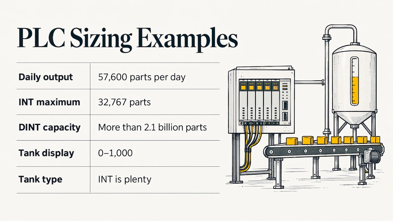
Now take a tank with a level scaled to 0 to 1000 for a display. An INT is plenty. Choosing a DINT is not wrong, but choosing a SINT would be, because 1000 is outside its range.
Signed vs unsigned integers
A signed integer uses one bit to represent sign, so its range straddles zero. An unsigned integer uses every bit for magnitude, so it starts at zero and goes about twice as high. Rockwell lists INT as 16-bit from -32,768 to 32,767 and UINT as 16-bit from 0 to 65,535, and its table gives matching pairs for the other widths.
When unsigned makes sense:
- Raw values from a device that can never be negative, such as a 16-bit encoder count or a register that reports 0 to 65,535.
- Bit-level work where the number is really a pattern, not a quantity.
When to stay signed:
- Any math that subtracts. An unsigned value that goes below zero wraps to a huge number instead of a small negative one, which can drive a valve or a motor to a surprising command.
- Values that mix with REALs and signed integers in the same expression.
A good default is signed unless a specific signal needs the extra range. Many Logix programmers use DINT almost everywhere for exactly this reason.
REAL and LREAL: decimals and precision
REAL is a 32-bit floating-point number and LREAL is a 64-bit one, per Rockwell’s table. What matters in practice is precision. PLCnext’s guide says REAL gives roughly seven significant digits and LREAL roughly fifteen.
Seven digits is plenty for a temperature of 182.46 degrees. It is not enough for a running total that climbs into the tens of millions, because the small increments you add each scan eventually fall below the precision and disappear. For totalizers, use a DINT (counting in small engineering units) or an LREAL where the platform supports it.
A second rule: do not compare two REALs for exact equality. Use a less-than or greater-than test, or check that the difference is inside a small band.
Bit strings: BYTE, WORD, DWORD and LWORD
Bit strings are for treating a group of bits as a unit. Siemens lists BYTE as 8 bits, WORD as 16 bits and DWORD as 32 bits. They look like integers in memory, but you use them differently: you address individual bits, mask them and shift them rather than do arithmetic.
Typical uses:
- A drive status word where each bit reports ready, running, faulted, at speed and so on.
- A control word sent to a device where each bit is a command.
- Packing a bank of alarms into one value to send to a SCADA system or HMI.
This connects directly to the idea of bit, byte, word and double word as sizes: 8 bits make a byte, two bytes make a word, and two words make a double word. Whether the content is a number or a set of flags depends on the type you declare.
Time and date types
Time types let the controller work with durations and timestamps without you doing the unit math. On Siemens S7-1200 controllers, TIME is a 32-bit IEC time value, DATE is a 16-bit date, TOD is a 32-bit time of day, and DTL is a 12-byte date-and-time structure.
Use them for timer presets, shift schedules, time-stamped events and data logging. Rockwell Logix controllers handle timers differently, with a TIMER structure holding a preset, accumulated value and status bits, so check what your platform expects before you port logic between brands.
STRING and CHAR: text in a PLC
Text is stored as a sequence of characters, and you decide how long it can be. In Machine Expert, string memory depends on the declared byte length: with no size given, the default is 80 bytes, and with Latin-1 storage each character takes one byte plus one extra byte for the string as a whole.
Two habits keep text from causing trouble. First, size strings to what you need: a 10-character part code does not need an 80-byte string repeated across 500 tags. Second, keep text out of fast logic. Strings are for recipes, labels, barcodes and messages, not for decisions made every scan.
Arrays and structures: organizing related data
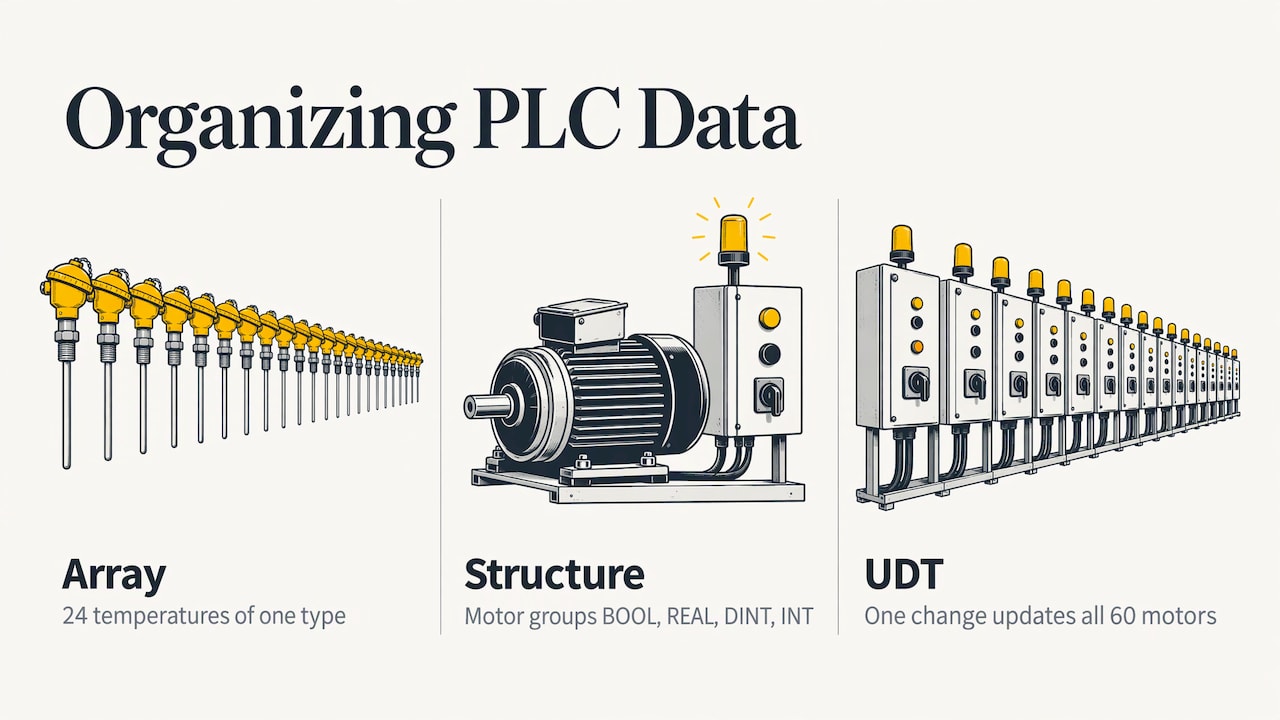
Once you have more than a handful of tags, individual types are not enough. An array is a list of values of one type, such as 24 temperatures. A structure combines different types under one name, such as a motor with a run command (BOOL), a speed setpoint (REAL), a running hours count (DINT) and a fault code (INT).
Siemens calls its reusable version a PLC data type, or UDT: a complex structure made of components of different data types, arrays or nested structures. Its documented advantages include simpler data exchange at block interfaces, grouping of process data, passing parameters as a single unit, and creating several data blocks with the same structure.
The maintenance payoff is the big one. When you change the UDT, every tag built from it follows. Add a “maintenance mode” bit to your motor type once and all 60 motors have it. The same idea applies to Logix user-defined types and add-on instructions.
Structure also helps when controllers share data. If you are passing tags between processors, see our walkthrough on setting up Studio 5000 produced and consumed data, where matching data types on both sides is essential.
How to choose the right data type
Start from the signal, not from the memory. Control.com’s practitioner guidance points to a simple pattern: Boolean tags for discrete I/O, floating-point real tags for analog process values, and integer types for calculations. Then use structures to organize related data.
A working checklist:
- Is it on/off? Use BOOL.
- Is it a whole number? Pick the integer width from the largest value you can imagine, then go one size up if the process might grow.
- Does it need decimals or engineering units? Use REAL. Use LREAL only when you truly need the extra precision and the platform supports it.
- Is it a group of flags? Use a bit string or a structure of BOOLs.
- Is it a duration or timestamp? Use the platform’s time types.
- Is it text? Use a STRING sized to the longest value you expect.
- Does the instruction accept it? Check the instruction’s parameter list before you finalize the tag.
That last step matters. Siemens advises that you choose a type the instruction parameter supports, and that you size any absolute address to match a supported data type.
Common data type mistakes and how to avoid them
Mixing types without thinking about conversion
Siemens states that the actual parameter must match a type supported by the instruction’s formal parameter, and that instructions accept only compatible types. If a tag does not fit, convert it explicitly instead of hoping the compiler or runtime will sort it out.
Watch the direction of the conversion. Schneider warns that converting a larger type to a smaller one may lose information. A DINT holding 70,000 will not survive being moved into an INT.
Overflow and wrap-around
Counters and accumulators that outgrow their type either wrap, fault or saturate depending on the platform. Size them for the worst case, not the typical case, and decide what should happen at the limit.
Using INT for analog values that need decimals
A 4-20 mA signal scaled into an INT gives you whole-number resolution only. If you need 0.1 degree resolution, either scale to tenths (so 182.4 becomes 1824) or use a REAL. Document whichever you choose, and make sure the HMI applies the same scaling.
Forgetting that generic types exist
Some function interfaces are written to accept a family of types. PLCnext groups its integer types under the generic ANY_INT, so a function that takes ANY_INT can handle the listed signed and unsigned integers. Knowing this saves you from writing five copies of the same function.
Mismatched types between PLC and HMI
The HMI reads whatever the tag holds. If the PLC tag is a DINT and the HMI object expects a REAL or a 16-bit value, you get odd readings or communication errors. Build the tag list once, confirm each type on both sides, and test the extremes. Our article on how an HMI communicates with a PLC program walks through that link in Rockwell’s FactoryTalk.
Perspective: why we teach data types first
When a new student shows us a program that “almost works,” the cause is a data type problem more often than a logic problem. A counter that stops at 32,767. A temperature that jumps by whole degrees. A value that reads correctly in the PLC and wrong on the screen.
That is why our courses start with the way the controller stores information, then move on to ladder logic. If you understand what is inside a tag, you can read any program, on any brand, and troubleshoot it faster. We build the lessons around real machines and real tag lists, because a table of ranges only sticks when you have watched a bad type break something.
Our training is designed for all skill levels, from students writing their first rung to maintenance technicians who need to find a fault at 2 a.m. We would rather you learn it once, properly, with practical examples, than patch around it for years.
the author
Practice what you read
Reading about ranges helps, but the types click when you build with them: declare a DINT counter, push it past its limit in a simulator, then fix it. Our Allen Bradley PLC training covers tags, data types and Studio 5000 in practical, step-by-step lessons for all skill levels.

If you want someone to look at your own program, a 90-minute PLC coaching session is $97, and our online PLC coaching starts from $67 per session. For ongoing learning, the Yearly PLC Training Membership is $192 per year. For team questions, you can start at our home page.
FAQ
What is the difference between INT and DINT in a PLC?
INT is a 16-bit integer with a signed range of -32,768 to 32,767. DINT is a 32-bit integer that runs from -2,147,483,648 to 2,147,483,647, per Rockwell’s data type table. Use DINT for counters and general math, and INT where a device or older controller works in 16-bit registers.
When should I use REAL instead of an integer?
Use REAL when a value needs decimals, such as temperature, pressure or flow in engineering units. Integers suit counts and whole-number calculations. Avoid REAL for large running totals, since it holds only about seven significant digits, according to PLCnext’s documentation.
What is a UDT in PLC programming?
A UDT, or user-defined type, is a reusable structure that groups tags of different data types under one name. Siemens describes it as a complex structure of components, arrays or nested structures. Changing the definition updates every tag that uses it, which keeps motors, valves or recipes consistent.
Are PLC data types the same on every brand?
The core types (BOOL, integers, REAL, STRING) are very similar, but names, default sizes and memory behavior differ. For example, Schneider reserves 8 bits for a BOOL. Always check the documentation for the platform you are programming.
Why does my PLC value look wrong on the HMI?
Usually the tag type or scaling differs between the controller and the screen. Confirm the data type on both sides, then check whether the value was scaled, for example tenths stored in an integer. Test the lowest and highest values to catch range issues.
Sources
- ABB: Data types
- Siemens: Data types (S7-1200 manual collection)
- Siemens: Basics of PLC data types (UDT)
- Rockwell Automation: Elementary data types
- Schneider Electric: Standard Data Types
- PLCnext: Data Types, Generic and Elementary
- Control.com: Applications of Data Structures and Data Types